


( 34 / 84 )
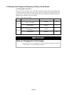
3.4 Switch Settings
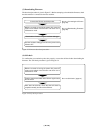
Here follows explanations of the switches of the M3062NT3-RPD-E.
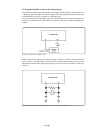
Tables 3.2 and 3.3 list how to set toggle switches SW1 to SW5 of the M30620T3-PRT board (MCU-
dependent 1), Table 3.4 lists how to set jumper switches JP1 and JP2.
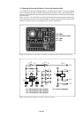
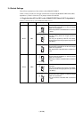
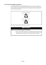
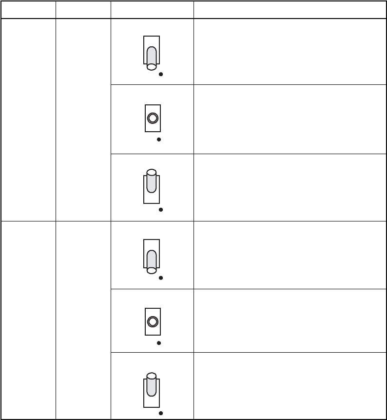
(1) Toggle Switches SW1 to SW5 on the M30620T3-PRT Board (MCU-dependent 1)
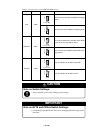
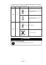
Table 3.2 Switch settings of the M3062NT3-RPD-E (1/3)
Signal Switch Setting Description
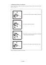
BYTE
SW1
SW2
CNVss
Use this setting when the target system is
connected.
Does not pull up/down pin BYTE of the MCU.
(Inputs the level of the target system to pin BYTE
of the MCU.)
Sets pin BYTE of the MCU to "H" when the target
system is unconnected.
Pulls up pin BYTE of the MCU with a resistance of
33 kΩ.
Sets pin BYTE of the MCU to "L" when the target
system is unconnected.
Pulls down pin BYTE of the MCU with a resistance
of 33 kΩ.
SW1 BYTE
L OPEN H
Sets pin CNVss of the MCU to "L" when the target
system is unconnected.
Pulls down pin CNVss of the MCU with a resistance
of 1 kΩ.
Use this setting when the target system is
connected.
Does not pull up/down pin CNVss of the MCU.
(Inputs the level of the target system to pin CNVss
of the MCU.)
Sets pin CNVss of the MCU to "H" when the target
system is unconnected.
Pulls up pin CNVss of the MCU with a resistance
of 1 kΩ.
(Factory-setting)
SW1 BYTE
L OPEN H
SW1 BYTE
L OPEN H
SW2
L OPEN H
(Factory-setting)
SW2
L OPEN H
SW2
CNVss
CNVss
CNVss
L OPEN H