


( 46 / 84 )
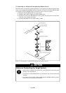
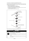
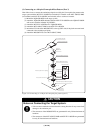
Figure 3.17 Connecting to a 100-pin 0.65-mm-pitch foot pattern (part 2)
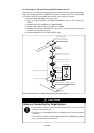
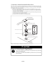
CAUTION
Notes on Connecting the Target System:
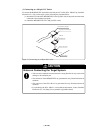
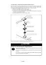
• Take care not to attach the converter board in a wrong direction. It may cause a fatal
damage to the emulation pod.
• The connectors of the M30800T-PTC are guaranteed for only 50 insertion/removal
iterations.
• The connectors of the M3T-100LCC-DMS and M3T-DUMMY100S are guaran-
teed for only 20 insertion/removal iterations.
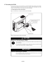
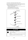
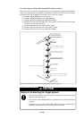
(5) Connecting to a 100-pin 0.65-mm-pitch Foot Pattern (Part 2)
Here follows how to connect the emulation pod probe to a 100-pin 0.65-mm-pitch foot pattern on the
target system with the M3T-DUMMY100S (not included). For details on the M3T-100LCC-DMS
(not included) and M3T-DUMMY100S (not included), refer to each user's manual.
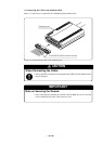
(1) Mount the M3T-DUMMY100S to the target system.
(2) Attach the M3T-100LCC-DMS to the M3T-DUMMY100S.
(3) Attach the CN2 side of the M30800T-PTC to the tip (CN2 side) of the pitch converter board
connected to the emulation pod probe.
(4) Attach the M30800T-PTC to the M3T-100LCC-DMS.
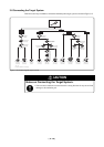
M30800T-PTC
Onboard evaluation
Flash version MCU etc.
M3T-100LCC-DMS (not included)
M3T-DUMMY100S
(not included)
100-pin 0.65-mm-pitch (100P6S-A) foot pattern
CN2 side
Ta rget system
No. 1 pin
(2)
(4)
(3)
(1)
Tip of pitch converter board
Tip of emulation pod probe