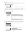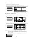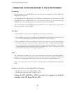
Communication buffer size
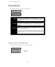
This function selects the maximum size of the input buffer.
When the selection of this function is completed, the printer is initialized.
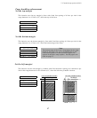
The buffer size affects the signal protocol in serial data communication. In these protocols the
printer's busy/ready state changes according to the data remaining values in the input buffer
described below.
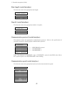
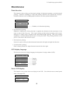
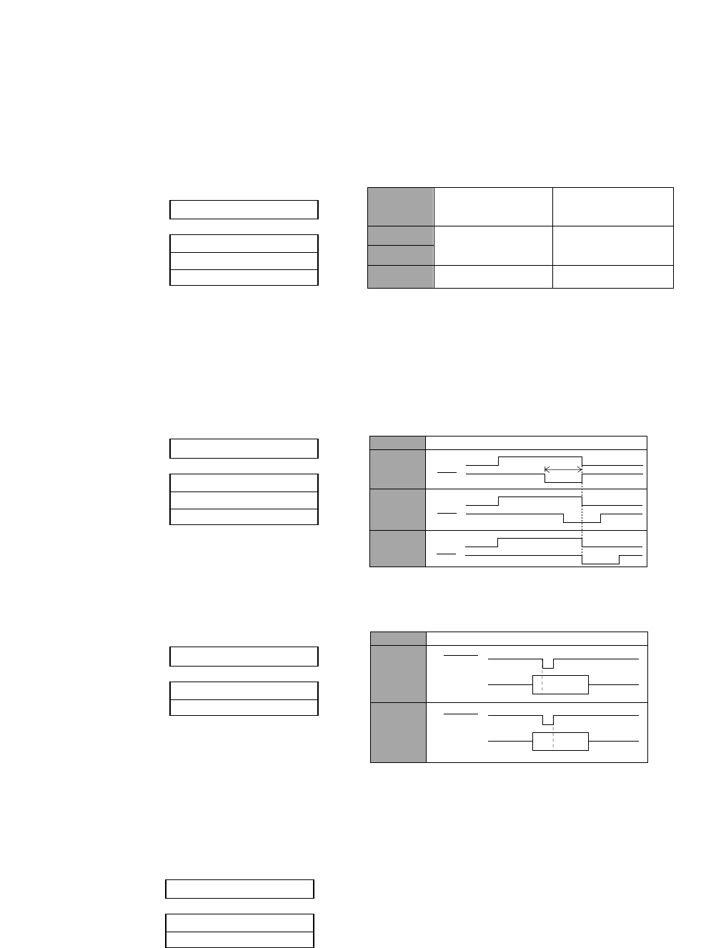
Busy/ACK timing (parallel interface)
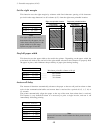
This function selects timing to activate the ACK signal for 8µ seconds (type 1) before, 4µ
seconds (type 2) before, or simultaneously synchronized (type 3) with the busy signal going
low.
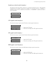
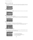
Data latch timing (parallel interface)
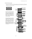
This function selects timing to latch the data signals at the rising edge (type R) or falling edge
(type F) of the STROBE signal.
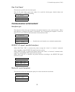
Setting of whether ERROR/PE signals are output or not
Setting is made whether or not ERROR and PE signals for the parallel interface are
output.
When "NO" is selected,
ERROR signal remains HIGH, and PE signal remains LOW, even if Error status.
71 BUFFER SIZE
B.SIZE: 64 KB
B.SIZE: 8 KB
B.SIZE: 128 B
72 BUSY/ACK
TIMING: TYPE 1
TIMING: TYPE 2
TIMING: TIPE 3
73 DATA LATCH
LTCH: TYPE F.
LTCH: TYPE R.
Note: When the remaining data capacity of the input buffer is
smaller than CIN, the printer becomes busy. This state continues
until the remaining capacity of the buffer is larger than CRN.
BUFFER
SIZE
64k byte
3k byte
Ready to Busy
(CIN)
1k byte
8k byte
128 byte
64 byte32 byte
Busy to Ready
(CRN)
BUSY
ACK
BUSY
ACK
BUSY
ACK
TimingType
TYPE 1
TYPE 2
TYPE 3
8 µs
Timing
Type
TYPE F
TYPE R
STROBE
DATA 1~8
STROBE
DATA 1~8
54
5. Extended setup options (71-74)
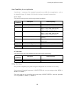
74 ERROR STATUS
STATUS SIG.:YES
STATUS SIG.:NO


