


18 Setting Up the 4000i
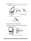
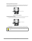
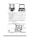
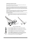
When you complete this step, your unit will look like this:
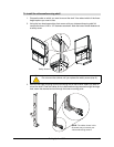
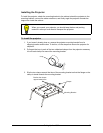
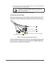
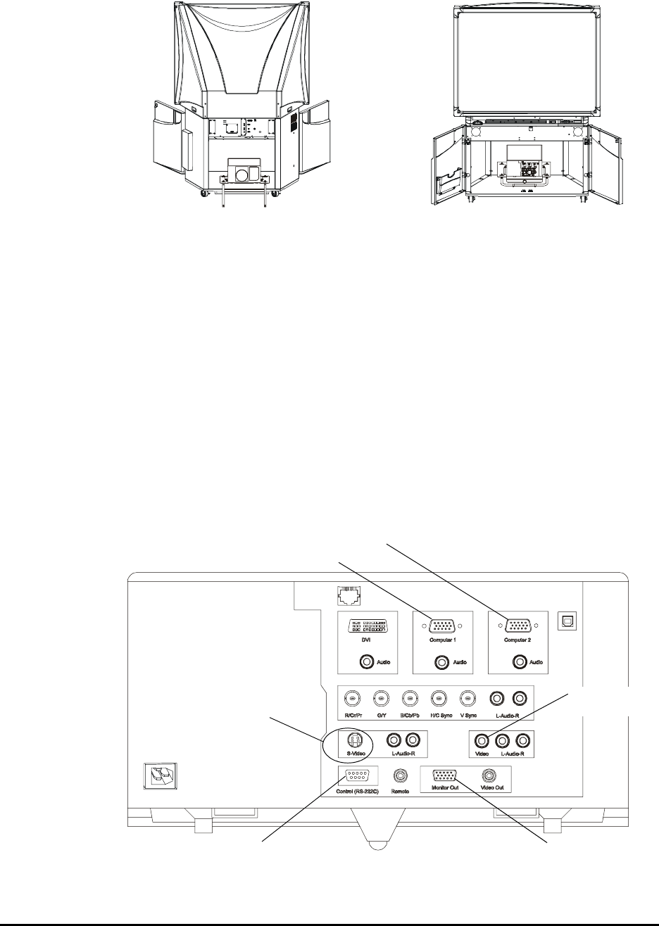
9. Locate the projector cable bundle that’s on the left side of the cabinet (when you’re
facing the front of the unit) and connect:
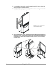
– the 15-pin male connector of the RGB video cable labeled RGB2 to the projector
port labeled Computer 2
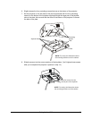
– the 15-pin male connector of the RGB video cable labeled RGB1 to the projector
port labeled Computer 1
– the mini-DIN connector of the S-video cable labeled S-video IN to the projector
port labeled S-Video
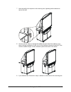
– the RCA plug of the composite video cable labeled Video IN to the projector’s
yellow Video jack
– the DB9F end of the RS-232 cable labeled PC Control to the Control port
– the 15-pin male connector of the RGB video cable labeled RGB OUT to the
projector port labeled Monitor Out
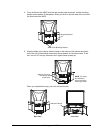
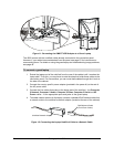
Back View
Front View
S-video Port
Composite
Video Jack
Computer 2 RGB Port
Monitor OUT Port
Computer 1 RGB Port
Control Port