


2
2-8
Hand-held Monitor User’s Guide – June 1994
GFK-0121E
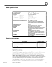
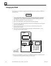
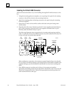
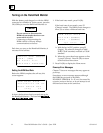
Installing the D-Shell HHM Connector
Follow the instructions below if you are installing the supplied D-shell connector on the
bus.
1. Using the mounting plate as a template, cut an opening in the panel for the mating
connector. Also drill two holes for the mounting hardware.
2. Attach the mounting plate and mating connector to the panel using the mounting
hardware supplied.
3. Secure the two ends* of the serial bus cable to the back of the panel using strain
relief brackets.
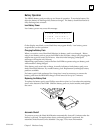
4. Strip the ends of the wires. Twist the two Serial 1 wires together and attach them to
pin 5 of the connector. Twist the Serial 2 wires together and attach them to pin 9.
Similarly, attach the Shield wire(s)* to pin 4.
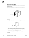
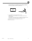
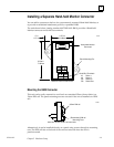
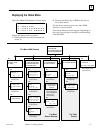
The following illustration shows connections for incoming and outgoing serial bus
cable. As with other devices, the HHM connector may be at either end of its bus. If it
is, there will only be one bus cable attached.
Mounting
Hardware
Bus
Cable
Bus
Cable
Strain
Reliefs
Shield
(Pin 4)
Mounting Surface
(rear view)
Mounting
Plate
Hand-held
Monitor
Connector
a42240c
SER 2
(Pin 9)
SER 1
(Pin 5)
Crimp
(Qty. 3)
Mating
Connector
When making bus connections, the maximum exposed length of bare wires should
be two inches. For added protection, each shield drain wire should be insulated with
spaghetti tubing to prevent the Shield In and Shield Out wires from touching each
other.
* If the HHM connector is at either end of its bus, it is necessary to install an
appropriate terminating resistor across the Serial 1 and Serial 2 wires. The Genius I/O
System and Communications User’s Manual lists appropriate terminating resistors for
each recommended bus cable type.