


4
4-7
GFK-0121E
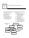
Chapter 4 Device Configuration: Overview
Configuring Field Control Station
1. From the HHM Main Menu, display the special
set of menus for Field Control.
A. If the Bus Interface Unit or Field Processor is
the current-selected device, press F2 (ana-
lyze) twice or F3 then F2.
B. If it is NOT the currently-selected device:
Select F2 (analyze) then F3 (Block/Bus
Status).
Press the F1 (nxt) or F2 (prev) key repeat-
edly to reach the serial bus address of the
BIU or Field Processor. Press F3 to make it
the active device. Then, press ∆Menu, fol-
lowed by F2 (Monitor/Control Ref).
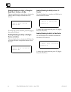
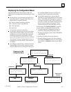
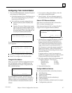
F1:Monitor
F2:Configuration
From this menu, press F2 (Configuration). This
menu appears:
F1:GENIUS CONFIG
F2:Module Config
F3:Previous Menu
Press F1 to configure the BIU/Field Processor.
Press F2 to configure individual modules.
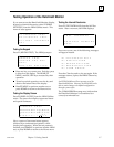
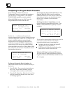
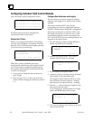
Change the Bus Address
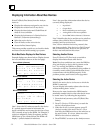
When you press F1 (Genius Configuration) from
the Configuration menu, the HHM shows the
serial bus address previously configured for the
BIU or Field Processor:
D e v i c e S B A
1 4
P r v > e n t r
If the bus address is correct, press F2 to go on.
Note: If a BIU or Field Processor has a Serial Bus
Address conflict on an operating bus, it will not
scan the modules in the station until the fault is
cleared.
1. If you want to change the address, enter the
new address using the keypad.
2. Press F4 (entr). An error message appears if
the number has been used for another device.
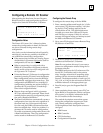
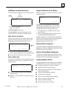
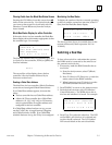
Select a PLC Reference Address
If the host is not a Series Six PLC or Series Five
PLC, no entry is necessary here.
If the host is a Series Six PLC or Series Five PLC,
assign an I/O or register reference address.
shows reference type
S t a t T b l Addr
< > I O 6 e n t r
OOOOO
1. Use the F3 key to toggle the selection of Series
Six I/O memory, Series Five I/O memory, or
register memory. (See the BIU/Field Processor
User’s Manual for information about memory
usage in the Series Five and Series Six PLC).
If I/O memory is used, the amount required is
equal to the number of bits of discrete data
PLUS analog data. Each analog reference used
consumes 16 points.
If register memory is used, an amount is re-
quired that is equal to the total number of bytes
of input data PLUS all of the output data
2. Key in the number of the block’s beginning I/O
or register reference. This may be:
Series Six I/O 1 to 993
Series Five I/O 1 to 2041
Registers 1 to 16383
3. Press the F4 (Entr) key.
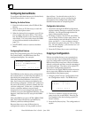
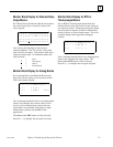
Configure Additional Features
On the screens that follow, select these features:
Fault Reporting
Genius bus redundancy
BSM Controller
Output default time (for redundancy)
CPU redundancy
Duplex redundancy: default mode for outputs
Configuration protection