


5
5-11
GFK-0121E
Chapter 5 Monitoring the Bus and its Devices
Monitor/Control Reference Displays for a PowerTRAC Block
For a PowerTRAC block, the Monitor/Control
Reference function displays:
16 screens, each showing the state of one Status
Input. This information is more easily dis-
played with the Monitor Block function,which
shows all 16 Status Inputs on one screen. See
page 5-7.
Individual labelled displays of the block’s current
calculated data values. For PowerTRAC block
version 2.3 or later, this includes the “low-priority
I/O”screens described on the next page.
16 screens, each showing the state of one of the
block’s Control Outputs. Control outputs are
also more easily displayed using Monitor Block.
PowerTRAC Data Sequence
The following table shows the sequence of
PowerTRAC block data that can be displayed on
the Monitor/Control Reference screens:
Input
Word
1
Status inputs
(16 screens in Monitor/Control Reference)
2
3
4
5
6
7
8
9
1
0
11
late
d Data
Voltage phase A to B
Voltage phase B to C
Voltage phase C to A
Voltage A to N (Line–to–neutral PTs only)
Voltage B to N (Line–to–neutral PTs only)
Voltage C to N (Line–to–neutral PTs only)
Current phase A
Current phase B
Current phase C
Auxiliary CT current
10
1
1
1
2
1
3
1
4
1
5
1
6
1
7
1
8
1
9
Calcul
ated
Current phase C
Auxiliary CT current
Active power phase A
Active power phase B
Active power phase C
Reactive power A
Reactive power B
Reactive power C
Total power factor
Accumulated power
20
21
22
23
24
25
26
27
28
29
30
31
32–64
Low–P riority I/O Data
Fundamental VARs phase A
Fundamental VARs phase B
Fundamental VARs phase C
Fundamental Power Factor, total
Harmonic VARS as % of V–A, phase A
Harmonic VARS as % of V–A, phase B
Harmonic VARS as % of V–A, phase C
Harmonic VARS as % of V–A, total
Line Frequency
Temperature Alar m Status
Extended Watt-hour accumulator (upper 5 digits)
Extended Watt-hour accumulator (lower 3 digits)
not used
Output
Word 1
Control outputs
(16 screens in Monitor/Control Reference)
For explanations of the data provided by a
PowerTRAC block, see the PowerTRAC Block User’s
Manual.
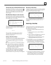
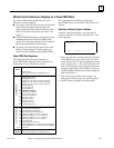
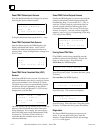
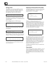
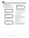
Selecting a Memory Type or Address
To select a specific data item, you can enter its
memory type and/or address. Press F2 (ref). This
screen appears:
M N T R __
t g l c h n g e n t r
1. Enter the reference number and press F3 (entr).
If the HHM is set up for a PLC host, I/O refer-
ences increment by 16 and word(register) refer-
ences increment by 1. For a PLC host, both I/O
and word references start at the first reference
assigned to the block. If the HHM is set up for
a PCIM/QBIM/GENI host, references begin at 1
and increment by 1.
2. The memory type blinks on the screen. To
change the memory type, use the F2 (tgl) key.
3. Press F3 (entr) to display the information.