


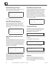

5
5-7
GFK-0121E
Chapter 5 Monitoring the Bus and its Devices
Monitor Block Display for a PowerTRAC Block
If the active device is a PowerTRAC block, the
HHM’s Monitor Block function displays the
following screens:
One screen showing the states of all of the
block’s Status Inputs.
Individual screens showing the block’s current
calculated data values. In the Monitor Block
function, these values are NOT labelled. It is
easier to display this information using the
Monitor/Control Reference function (F2), be-
cause those displays are labelled.
One screen showing the states of all of the
block’s Control Outputs.
On each of these screens, you can press F1 ( > ) to
display next screen, or press F2 (ref) and enter a
reference location to display a specific screen. For
a sequential list of the PowerTRAC block data, see
page 5-11.
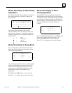
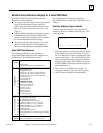
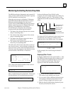
Status Inputs
The Monitor Block function first displays the
PowerTRAC block’s Status Inputs:
R E F (inputreferences) I
123456789O123456
OOO11OOOOOO1OOOO
> ref
Line 2 indicates each of the 16 possible bit
locations for status data. Lin e3 shows the current
states of all inputs.
Bits 1 – 3 indicate the status of table data transfer,
for datagram communications.
Bit 4 = 1 indicates the block has captured an over-
current event.
Bit 5 should always be 1, indicating that the block’s
phase-lock loop is synchronized with the
incoming AC voltage.
Bit 12 = 1 means the overcurrent event indicated
by bit 4 occurred on phase A.
Bit 13 = 1 means the overcurrent event indicated
by bit 4 occurred on phase B.
Bit 14 = 1 means the overcurrent event indicated
by bit 4 occurred on phase C.
Bit 15 = 1 means the overcurrent event indicated
by bit 4 occurred on the auxiliary current
line.
Bit 16 = 1 indicates an internal calculation has re-
sulted in an out-of-range value. The block
should be reconfigured to prevent this.
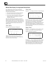
Calculated Data
After the Status Inputs, the HHM displays the
block’s calculated data. If the PowerTRAC Block is
version 2.3 or later, this includes the additional
“low-priority I/O” data listed on page 5-11.
R E F (input reference) I
1 1 7
> r e f
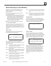
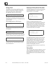
Control Outputs
After the calculated data screens, the HHM’s
Monitor Block function displays the PowerTRAC
block’s Control Outputs. You can also display this
data by using the F2 (ref) key to select output 1.
You may need to toggle (F2) the memory type.
R E F (outputreferences) O
123456789O123456
OOOOOOOOOOOOOOOO
> ref
Line 2 indicates each of the 16 possible bit
locations for Control Outputs. Line 3 shows the
current state of each Control Outputs. These
outputs are communications handshaking bits,
sent from the CPU to the block for certain
datagram communications. Information about
these outputs is in the PowerTRAC Block User’s
Manual.