


41388601TH Rev.2 127 /
0 Printout colors different from the original
• Are the LED head lens contaminated?
Yes Clean the LED head lens.
▼
• No Is each LED head assembly connected to the junction board (Y73 PWB) correctly?
No Check the cable connection (between each LED head and the junction board) and connect
the LED assy to the junction board correctly.
▼
• Yes Is +3.8V supplied to the following HEADPOW connector pins of the junction board (Y71
PWB)?
+3.8V: Pin 1, 2, 3, 4, 5, 6, 7, 8
• Yes Is +3.8V supplied to each LED head assembly from the junction board (Y71 PWB)?
YPOW connector Pin 3 : LED head assembly yellow
MPOW connector Pin 3 : LED head assembly magenta
CPOW connector Pin 3 : LED head assembly cyan
BPOW connector Pin 3 : LED head assembly black
No Replace the junction board (Y71 PWB).
▼
• Yes Check the cable connection, or replace the LED head assembly.
▼
• No Check the cable connection, or replace the low-voltage power supply unit. Recovered?
Yes End
▼
• No Is +32V supplied to the POWER connector of the engine board (K73 PWB)?
+32V; Pin 7, 8, 9, 10
No Check the cable connection, or replace the low-voltage power supply unit.
▼
• Yes Is +32V supplied to HVOLT connector pin 5 of the engine board (K73 PWB)?
No Replace the engine board.
▼
• Yes Check the cable connection, replace the high-voltage power supply unit or belt cassette
assembly. Recovered?
Yes End
▼
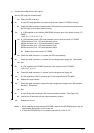
• No Is each ID terminal connected to the contact assembly correctly? (See Figure 6.3.)
No Connect the ID terminals with the contact assembly correctly.
▼
• Yes Replace the ID unit.
Notes: 1. When replacing the engine board (K73 PWB), demount the EEPROM chip from the old
engine board and remount it on the new one.
2. In case the EEPROM chip is not replaced, see Item (2) in Sec. 6.5.2.