


41388601TH Rev.2 15 /
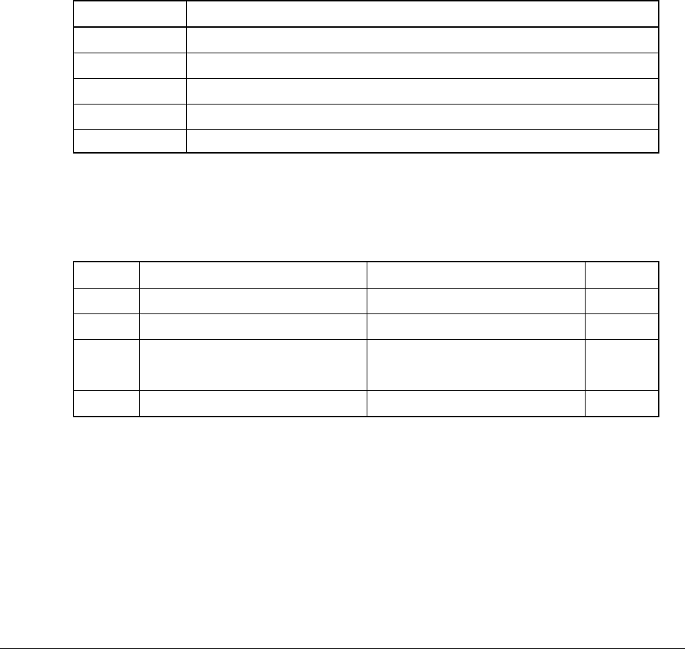
Output voltage Use for
+3.3 V Logic circuit power supply
+3.8V Logic circuit power supply
+5 V Motor and drive voltage for high-voltage power supply
+32 V OP Amp, High-voltage power supply
+12 V LED head
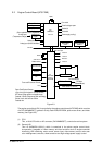
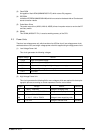
Output Voltage Use for Remarks
CH -900 to -1400±50V Voltage to charging roller
DB Y, M, C: -10 to -400V/+300V Voltage to developing roller
K: -10 to -400V/+300V
SB Y, M, C: -100 to -700/0V Voltage to toner supplying roller
TR 0 to 7KV Voltage to transfer roller Variable
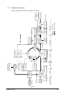
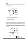
(2) High-Voltage Power Unit
This circuit generates the following 34V or more voltages, which are required for electropho-
tographic process, according to control sequences from the control board.
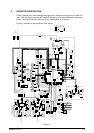
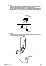
2.3 Power Units
There is a low-voltage power unit, which consists of an AC filter circuit, low-voltage power circuit
and heater driver circuit, and a high-voltage power unit which supplies a high-voltage power circuit.
(1) Low-Voltage Power Unit
This circuit generates the following voltages:
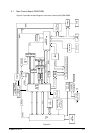
(3) Flash ROM
8 megabits of flash ROM (MBM29F800TA-70) which stores PU programs.
(4) EEPROM
4 kilobits of EEPROM (NM93C66N-NW) which is mounted on the board with an IC socket and
stores correction values.
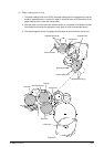
(5) Pulse Motor Driver
The pulse motor driver (A2918, A2919, A3955) drives nine pulse motors to revolve the EP
and carry media.
(6) SRAM
This SRAM (62256LFP-7LL) is used as working memory of the CPU.