


Owner’s Manual Rev 1.0 Page 29 of 29
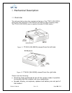
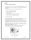
2. Electrical Description
All electrical connections to the TT4031 (SE-GM29) are designed to meet
the standard air (4 kV) and contact (8 kV) discharge ESD tests, of
EN 301 489-1.
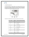
The modem uses the following industry standard connectors:
RJ11 6-way (power connector)
RJ9 4-way (handset connector)
SIM card reader
FME male coaxial jack (antenna connector)
Sub-D socket, 9 pin (RS232 serial port)
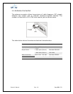
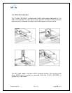
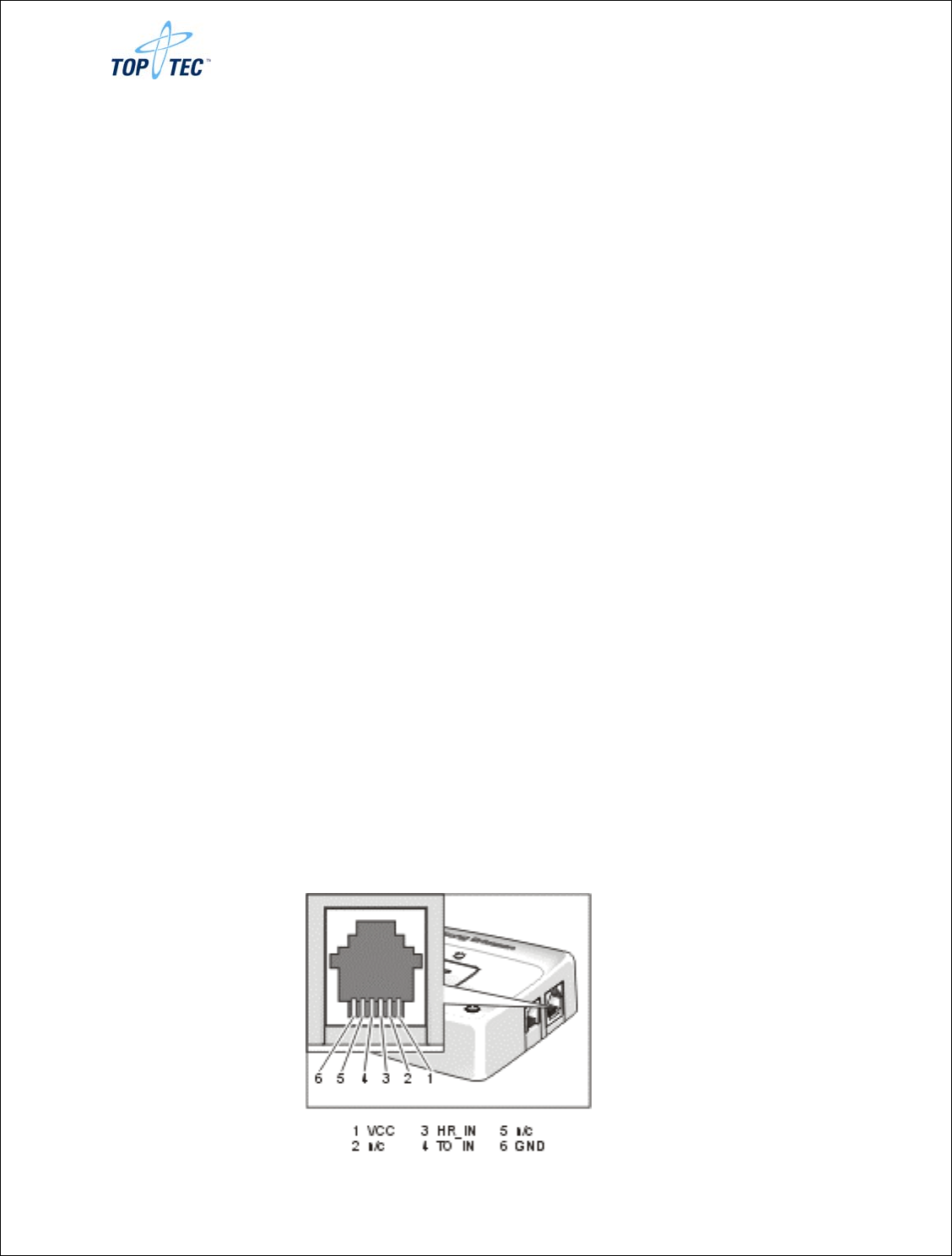
2.1 Power Connector
An RJ11 6-way connector, as shown and described below, serves as a
means of supplying and controlling d.c. power to the modem.
The supply voltage, VCC, required by the modem is in the range 5 V - 32 V
d.c. Application of the supply voltage does not switch the modem on. To do
so an additional active-high control signal, TO_IN, must be applied for
> 0.2 s .
A second active-high control signal, HR_IN, can be used to switch the
modem off when applied for 1 - 2 seconds, or can be used to perform a
hardware reset when applied for > 3.5 s.
TO_IN and HR_IN are referenced to GND (pin 6 on the connector).
VCC and GND are reverse polarity and overvoltage protected