


AR-B7041 User¡¦s Guide
2-6
2.4.1 Watchdog Timer Setting
The watchdog timer is a circuit that may be used from your program software to detect crashes or hang-ups.
Whenever the watchdog timer is enabled, the LED will blink to indicate that the timer is counting. The watchdog
timer is automatically disabled after reset.
Once you have enabled the watchdog timer, your program must trigger the watchdog timer every time before it
times-out. After you trigger the watchdog timer, it will be set to zero and start to count again. If your program fails
to trigger the watchdog timer before time-out, it will generate a reset pulse to reset the system.
The factor of the watchdog timer time-out constant is approximately 6 seconds. The period for the watchdog timer
time-out period is between 1 to 7 timer factors.
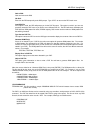
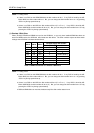
If you want to reset your system when watchdog times out, the following table listed the relation of timer factors
between time-out period.
Time Factor Time-Out Period (Seconds)
80H 3
81H 6
82H 12
83H 18
84H 24
85H 30
86H 36
87H 42
Table 2-1 Time-Out Setting
2.4.2 Watchdog Setting
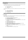
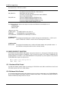
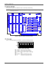
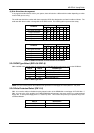
(1) Reset Signal Output of Watchdog Timer (J1)
J1 is used to connect to reset header of main board or CPU card.
1 2
J1
1 -WDRST
2 -WDRST
Figure 2-2 J1: Reset Signal Output of Watchdog Timer
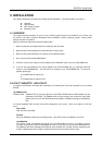
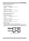
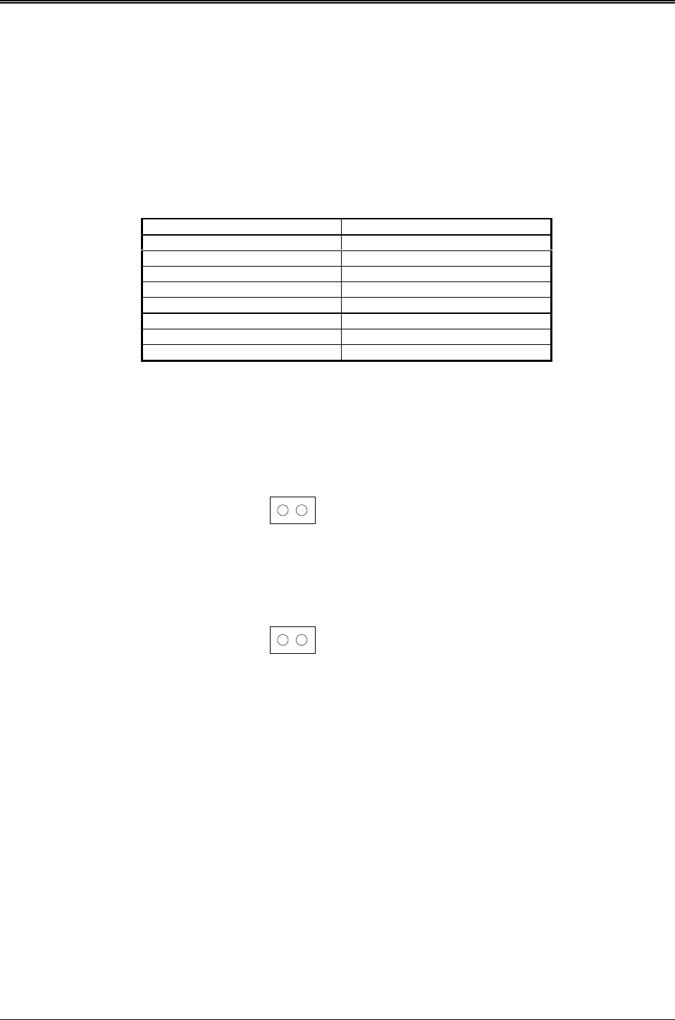
(2) Watchdog LED Header (J2)
1 2
J2
1 LED+
2 LED-
Figure 2-3 J2: Watchdog LED Header
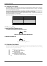
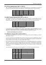
2.4.3 Watchdog Timer Enabled
To enable the watchdog timer, you have to output a byte of timer factor to the watchdog register whose address is
base port+3m 76h or 77h. The following is a BASICA program which demonstrates how to enable the watchdog
timer and set the time-out period at 24 seconds.
1000 REM Points to command register
1010 WD_REG% = BASE_PORT% + 3
1020 REM Timer factor = 84H
1030 TIMER_FACTOR% = %H84
1040 REM Output factor to watchdog register
1050 OUT WD_REG%, TIMER_FACTOR%
.,etc.