


AR-B7041 User¡¦s Guide
3-2
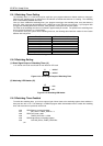
3.2 SWITCH SETTING
We will show the locations of the AR-B7041 switch, and the factory-default setting.
CAUTION: The switch setting needs to adjust with the jumpers setting, make sure the jumper settings and the
switch setting are correct.
BAT-OUT
1
1
2
3
M1
M2
M3
M4
MEM1
MEM8 MEM7
MEM6 MEM5
A B C
MEM2MEM3MEM4
WD
EN
+
1
EC
NC
+
-
+
-
RST
1
1
+
+
-
1
2
3
A
B C
1
2
3
CB
A
A B C
1
2
3
H8
JP1
U13 U14 U15
U16
U4 U5 U6
U7
J5
J3
J4
JP2
P5
P6
P1
P2
P7
P8
P3P4
U21
U9
J6
U12
U10
J1
J2
U11
SW1
U17
U19
U18
U26
U8
U25
U22
U27
U24
H7
H6
H5
BAT1
H3
CN1
LED2LED1
H9H2
BUS1
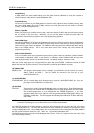
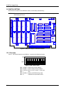
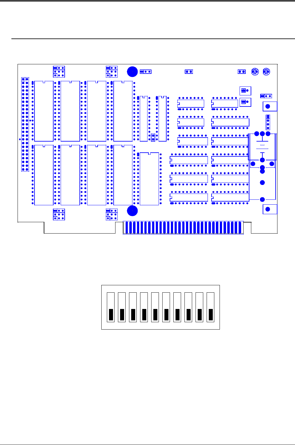
Figure 3-1 AR-B7041 Jumper & Connector Location
3.2.1 Overview
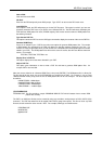
There is 1 DIP Switch located on the AR-B7041. It performs the following functions:
ON
1 2 3 4 5 6
OFF
7 8 9 10
Figure 3-2 SW1: Switch Select
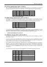
SW1-1 & SW1-2 Set the base I/O port address
SW1-3 & SW1-4 Set the starting memory address
SW1-5, SW1-6 &
SW1-7
Set the drive number of solid state
disk
SW1-8 & SW1-9 Set the used ROM memory chips
SW1-10 ROM disk write protected function