AR-B7041 User¡¦s Guide
3-16
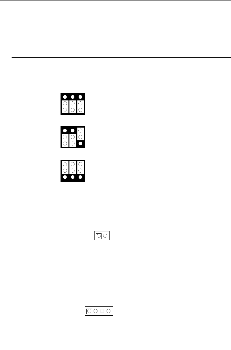
3.5.1 Memory Type Setting (JP1 ~ JP4)
The AR-B7017 provides 4 sockets for memory chips.
l JP1: is used to configure the memory type of MEM1 & MEM2
l JP2: is used to configure the memory type of MEM3 & MEM4
l JP3: is used to configure the memory type of MEM5 & MEM6
l JP4: is used to configure the memory type of MEM7 & MEM8
CAUTION: When the power is turned off, please note the following precautions.
1. If your data has been stored in the SRAM disk, do not change the jumper position or data will be
lost.
2. Make sure jumpers are set properly. If you mistakenly set the jumpers for SRAM and you have
EPROM or FLASH installed, the EPROM or FLASH will drain the battery’ s power.
EPROM (128KX8, 256KX8, 512KX8)
5V/12V FLASH (64KX8M 128KX8, 256KX8)
Factory Preset
2
1
3
A B C
5V FLASH (512KX8 only)
2
1
3
A B C
SRAM
2
1
3
A B C
JP1~JP4
JP1~JP4
JP1~JP4
Figure 3-17 JP1~JP4: Memory Type Setting
3.5.2 Battery Setting
(A) Battery Output Connector (JP5)
1 Battery+
2 Battery-
JP5
1 2
Figure 3-18 JP5: Battery Output Connector
(B) External Battery Connector (JP6)
There are two external battery connectors (JP5 and Jp6) on the AR-B7017. JP5 is used to supply power to the
SRAM chips when system power is turned off and you want to remove the AR-B7017 module from AR-B7041
temporarily. JP6 is a 4-pin external battery connector and is designed to supply the power of SRAM when the AR-
B7017 is going to be removed from the AR-B7041 for a long time. The voltage range of the external battery should
be 3.6VDC to 6 VDC. The pin assignments of the JP6 are defined as follows:
1 Battery+
2 Battery-
JP6
4 Battery-
3 Battery+
1 432
Figure 3-19 JP6: External Battery Connector


