


AR-B7041 User¡¦s Guide
3-11
3.4.2 Large Page 5V FLASH Disk
If you are using large page 5V FLASH as ROM disk, it is the same procedure as step 1 to step 4 of using the UV
EPROM.
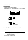
(1) Switch and Jumper Setting
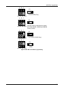
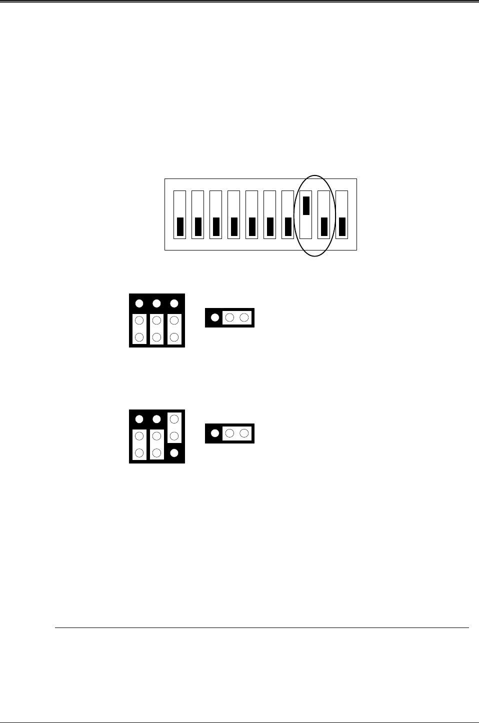
Step 1: Use jumper block to set the memory type as ROM (FLASH).
Step 2: Select the proper I/O base port, firmware address, disk drive number and large page 5V FLASH type
on SW1.
Step 3: Insert programmed EPROM(s) or FLASH(s) chips into sockets starting at MEM1.
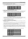
ON
1 2 3 4 5 6
OFF
7 8 9 10
Figure 3-11 5V Large FLASH (29FXXX) Switch Setting
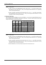
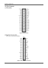
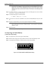
M1, M2, M3, & M4
5V FLASH (64KX8, 128KX8 and 256KX8)
(Factory Preset)
5V FLASH (512KX8 Only)
M1, M2, M3, & M4
1
2
3
A B C
1
2
3
A B C
1 2 3
JP1
1 2 3
JP1
Figure 3-12 Large Page 5V FLASH Jumper Setting
(2) Software Programming
And then, you should create a PGF and generate ROM pattern files by using the RFG.EXE.
Step 1: Making a Program Group File (*.PGF file)
Step 2: Generate ROM pattern files
Turn off your system, and then install FLASH EPROMs into the sockets.Step 3:
NOTE: Place the appropriate number of FLASH EPROM chips (the numbers depends on the ROM
pattern files generated by RFG.EXE) into the socket starting from MEM1 and ensure that the
chips are installed in the sockets in the proper orientation. Line up and insert the AR-B7041
board into any free slot of your computer.
Step 4: Turn on your system, and Program FLASH EPROMs.