AR-B7041 User¡¦s Guide
5-3
The AR-B7041 provides 8 sockets for memory chips. Each AR-B7041 card also could be piggy-backed 1 AR-
B7017 to have more sockets for more memory capacity. Five combinations of AR-B7041 and AR-B7017 are valid,
they are as following:
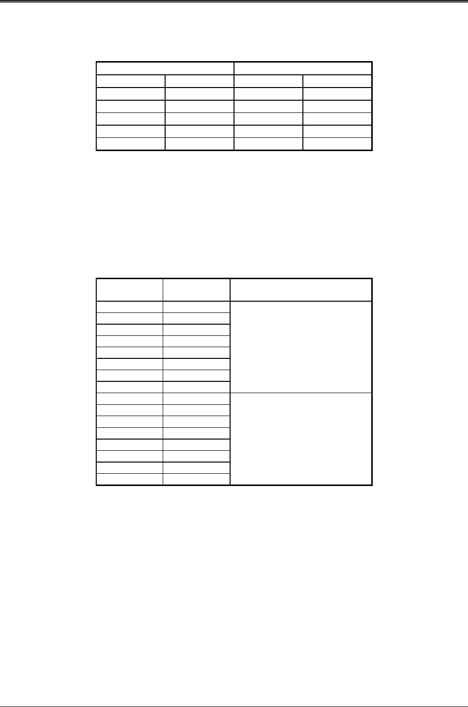
First Second
AR-B7041 AR-B7017 AR-B7041 AR-B7017
Installed None None None
Installed None Installed None
Installed Installed None None
Installed Installed Installed None
Installed Installed Installed Installed
The AR-B7017 accepts the same kinds of memory chips that the AR-B7041 uses. Every AR-B7017 provides eight
32-pin JEDEC DIP sockets for a maximum of 4MB FLASHs, EPROMs or SRAMs. The AR-B7017 is installed on
the AR-B7041 through the piggyback connector CN1. When you create the ROM pattern files with extensions
exceeding .R08, the files with extensions .R01 to R08 are placed in the first AR-B7041 card from MEM1 to MEM8,
and the files with extensions .R09 to .R16 go into the AR-B7017 installed on the first AR-B7041 or the second card
from MEM1 to MEM8 if no AR-B7017 module, etc.
If no AR-B7017 is used, the locations and sequence of memory chips are listed on the following table:
Pattern
Number
Socket Name Card of Sockets Located
R01 MEM 1
R02 MEM 2
R03 MEM 3
R04 MEM 4
R05 MEM 5
R06 MEM 6
R07 MEM 7
R08 MEM 8
First AR-B7041
R09 MEM 1
R10 MEM 2
R11 MEM 3
R12 MEM 4
R13 MEM 5
R14 MEM 6
R15 MEM 7
R16 MEM 8
Second AR-B7041


