


Disk Boards and Components 5-11
5
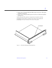
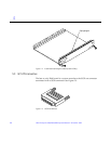
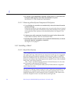
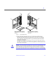
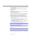
Figure 5-7 Board Replacement
2. Ensure that both extraction levers are in the insert position (arrow
pointing outward) and that the quarter-turn access slots are unlocked
(arrow indicates unlocked position) as you slide the board toward the
centerplane receptacles.
See Figure 5-4 on page 5-7 and Figure 5-5 on page 5-7. The board will not
seat fully unless the levers are in this starting position and both quarter-turn
access slots are unlocked.
Caution – DO NOT FORCE any board into a slot; this can cause damage to the
board and system. The board should insert and seat smoothly. If it binds,
remove the board and inspect the card cage slot for any obvious obstructions.
Also inspect both the board and the centerplane for bent pins or other damage.
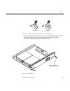
Board orientation for insertion
in the cabinet rear (component
side up)
Board orientation for insertion
in the cabinet front (component
side down)
!