


Non-Chassis Field Replaceable Units (FRUs) E-25
E
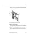
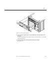
3. Place the rear chassis on the front chassis.
4. Replace the screws around the center of the main chassis.
• For the Enterprise 6000 system, there are a total of 32 screws, 8 per side.
• For the Enterprise 5000 system, there are a total of 26 screws.
Warning – Use care when lifting the Enterprise system chassis. It weighs
approximately 100 pounds.
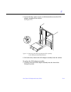
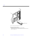
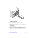
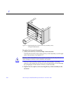
5. Slide the main chassis into the system cabinet.
Use the bottom rails as a guide.
6. Replace the four screws on each side of the system cabinet that attach the
bottom rails to the main chassis.
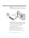
7. Replace the top rails.
a. Tighten the four screws on each side attaching the top rail to the main
chassis.
b. Replace the two screws on each side attaching the top rail to the system
cabinet.
8. Replace the SCSI adapter assembly, the key switch adapter assembly, and
the 200/240V fan tray assembly.
See Section E.1.6, “SCSI Tape Adapter PCS Assembly,” Section E.1.7, “Key
Switch Adapter Assembly, and Section E.1.8, “Fan Tray Assembly,
200/240V” for information on replacing these assemblies.
9. Replace all the boards and power supplies.
See Chapters 3-6 for information on replacing the boards and Chapter 7,
“Power Supplies,” for information on replacing power supplies.
10. Connect any remaining cables to the Enterprise system main cabinet.
11. Replace any assemblies above and below the Enterprise system.
Refer to the respective service manuals for further information.
12. Replace the front bezel, hinged door and rear screen panel.
See Chapter 13, “Preparing for Service,” for information on replacing these
assemblies.
13. Power on the Enterprise system.
See the power on instructions in Chapter 12, “Powering Off and On.”
!