


Connectors G-3
G
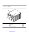
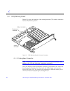
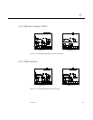
Figure G-2 CPU/Memory Board Centerplane Connector Location
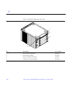
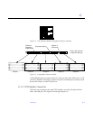
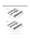
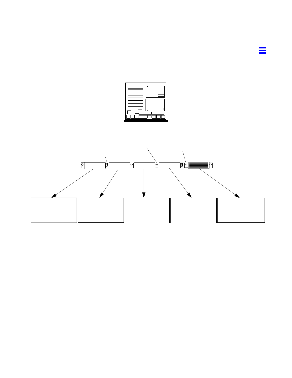
Figure G-3 Centerplane Connector Detail
A three-bladed power section results in 12 pins on the board. There are six, 120
pin rows, labeled A through F, spread across the remaining five sections; each
section has 24 pins of each 120 pin row.
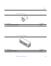
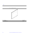
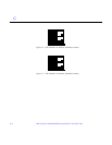
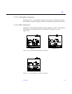
G.1.2 CPU Module Connectors
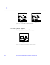
There are two connectors for each CPU module, one with 144 pins and the
other with 288 pins. See Figure G-4 through Figure G-6.
(Rear view of board
1----------------- ---- --- - 24
49-- ---------------- -----72
73- -- ---------------------96
97 ------------- ------ -- --120
F
E
D
C
B
A
Guide pin
receptacle
(2 per board)
Spacer (4
per board)
Pre-power section
1------------- ---- - --- ----24
1-------- --- ------ -------- 24
1---------------- - ------- - 24
1------- ------ ------- ----- 24
1------- ------ -------- ---- 24
25--------------- --- --- - -48
25- -------- ----- --- ----- 48
49------- ------ ----------72
73---- ------- -------------96
97 -- ---- ------ -----------120
97- ------- ----- --- -------120
97------ --------- -- -- ----120
97 ------ --- ------ --------120
97 --- ------ - -- ----------120
73--- ---- -----------------96
73---- ---- ----------------96
73-- ------ ----------------96
73 ------ ------------------96
49- ------------------- ---72
49----- ----- -------------72
49-- ------ ---------------72
49---- --- ---- -----------72
25-------- -- --------- --- -48
25------------ - -------- - -48
25------- ----------- --- - -48
25------------ ------- -- - -48
Section 1 Section 2
Section 3
Section 4 Section 5
component side up)