


E-2 Ultra Enterprise 6000/5000/4000 Systems Manual—November 1996
E
E.1 Enterprise 6000/5000 Systems
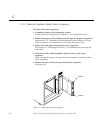
E.1.1 System Cabinet Fan Tray Assembly
You must remove the fan tray screen to reach the assembly.
To remove the fan tray screen:
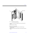
1. Locate the system cabinet fan tray assembly at the right rear of the
cabinet.
2. Loosen the top screw on the left and the three screws on the right of the
fan tray screen.
It is not necessary to remove these four screws since the screen has slotted
screw holes.
3. Remove the two bottom screws on the left of the fan tray screen.
Removing these screws will ensure adequate clearance.
4. Lift the screen up until the slotted screw holes clear the screw heads, and
set it aside.
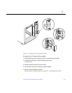
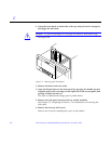
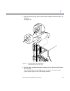
To remove the fan tray assembly:
1. Remove the power cable and fan cable assembly.
2. Loosen the two captive screws at the top and bottom of the fan tray
assembly.
See Figure E-1.