


Clock Board 6-7
6
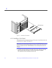
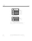
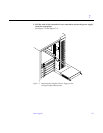
2. Ensure that both extraction levers are in the outward position as you slide
the board toward the backplane connectors.
See Figure 6-2. The board will not seat fully unless the levers are in this
starting position.
Caution – DO NOT FORCE any board into a slot; this can cause damage to the
board and system. The board should insert and seat smoothly. If it binds,
remove the board and inspect the card cage slot for any obvious obstructions.
Also inspect both the board and the backplane for bent pins or other damage.
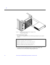
3. Use the extraction levers to seat the board.
Simultaneously swing both levers into the locked position. Do not press on
board front panel to seat it—doing so will damage the connector pins.
4. Secure the board to the chassis using the two captive screws, one on each
side.
5. Connect any applicable interface cables to the front panel of the board.
6. Turn on system power. See Chapter 12, “Powering Off and On," for this
procedure.
7. Boot the system.
!