


I/O Boards and Components 4-11
4
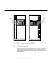
4.5.2 Removing a Board
4.5.2.1 Removing a Board from a Powered On System
Caution – Remove a board from a powered on system only after the ASR
software has disabled the board. If a board has not been disabled by the ASR
software, then the operating system should be halted and the system powered
off prior to board removal. See Chapter 12, “Powering Off and On” and then
Section 4.5.2.2, “Removing a Board from a Nonpowered On System.”
1. Ensure that the board has been disabled by the ASR software. See
Section 4.4, “Hot-Plug Feature.”
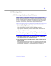
Once disabled by ASR, one of two results occurs:
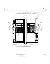
• The three LEDs on the board are not lit (board has no power).
• The outer two green LEDs are not lit and the middle yellow LED is lit
(board in low power mode).
Note – System software operates such that the LED pattern described is the
same for a board that is component side down (installed in front of card cage)
or component side up (installed in rear of card cage).
2. Unfasten any cable connectors from the front panel and set them aside.
Label cables to identify them for reconnection later.
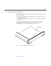
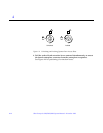
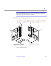
3. Use a Phillips #1 screwdriver to mechanically release the board from the
system card cage.
Insert the screwdriver into each quarter-turn access slot (the slots are located
on the left and right sides of the board‘s front panel) and then turn a quarter
turn so that the arrow points to the unlocked position. See Figure 4-8.