


CPU/Memory Boards and Components 3-19
3
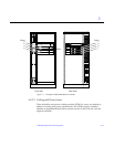
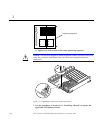
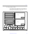
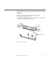
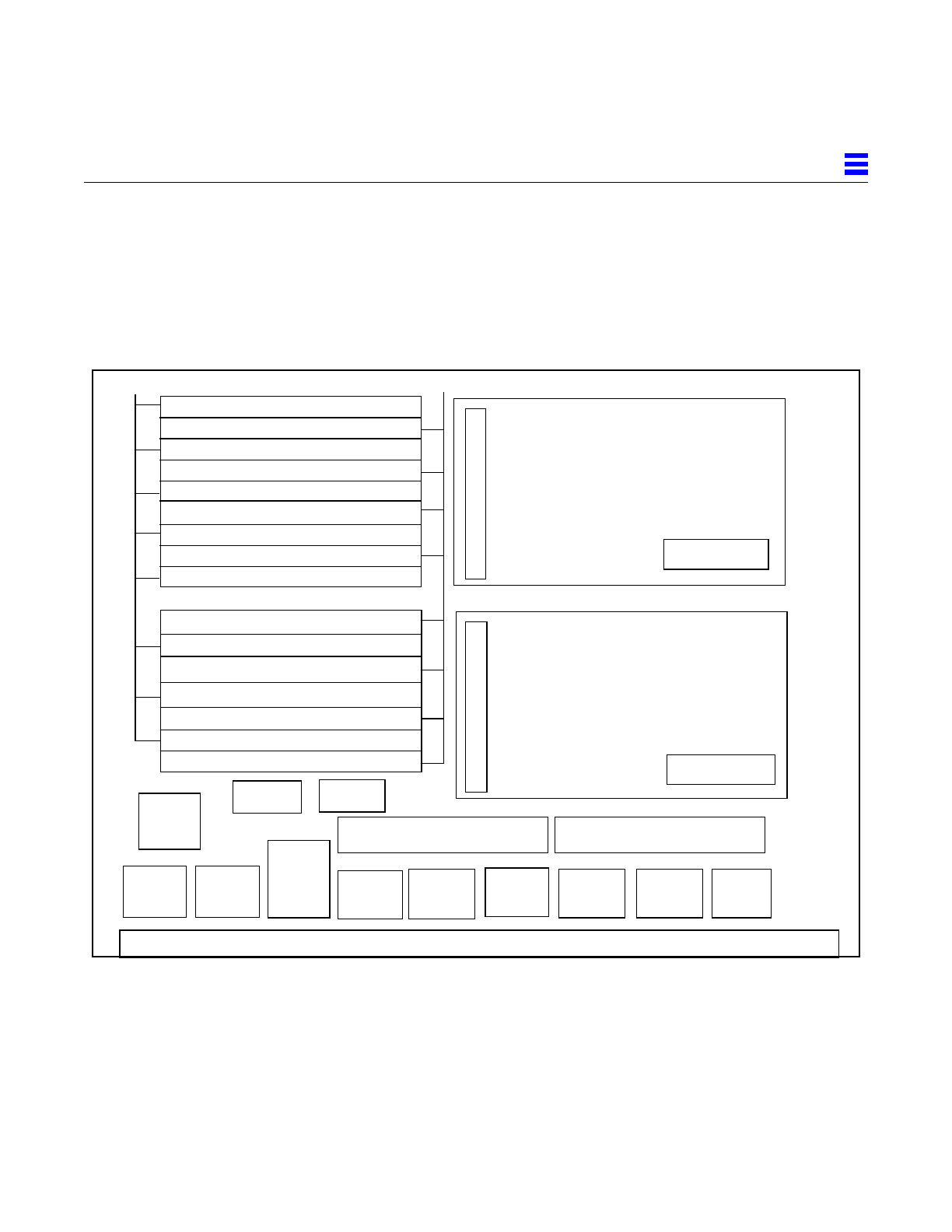
3.4.5 Memory Modules (SIMMs)
The CPU/Memory board has 16 SIMM sockets, which are divided into two
banks of 8 SIMMs each, Bank 0 and Bank 1. Bank 0 and Bank 1 SIMMs occupy
alternate slot locations; Bank 0 SIMMs are in the even numbered slots, and
Bank 1 SIMMs are in odd numbered slots. See Figure 3-13.
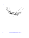
Figure 3-13 Layout of CPU/Memory Board
DC
DCDC
DC
DC
DC
DC
DC
AC
B0-J3100
B0-J3200
B0-J3400
B0-J3500
B0-J3300
B0-J3600
B0-J3800
B0-J3700
B1-J3101
B1-J3501
B1-J3301
B1-J3401
B1-J3601
B1-J3701
B1-J3801
B1-J3201
SRAM
FHC
35W DC2DC
35W DC2DC
144 connector
144 connector
288 connector
288 connector
720 centerplane connector
Bank 0
Bank 1
CPU1
CPU0
SRAM