


13-8 Ultra Enterprise 6000/5000/4000 Systems Manual—November 1996
13
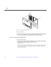
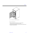
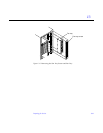
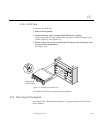
13.3.7 Fan Tray
To remove the screen protecting the fan tray cables:
1. Loosen the top screw on the left and the three screws on the right.
It is not necessary to remove these four screws since the screen has slotted
screw holes.
2. Remove the two bottom screws on the left.
Removing these screws will ensure adequate clearance.
See Figure 13-5.
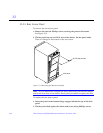
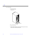
3. Lift the screen up until the slotted screw holes clear the screw heads.
Lift out the screen and set it aside.
To replace the fan tray screen cover, reverse these instructions.
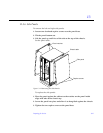
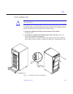
To remove the fan tray:
1. Loosen the two captive fasteners at the top and bottom of the tray.
2. Pull the fan tray back, tilting the top out so that it clears the chassis.
Lift the fan tray out.
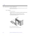
3. Remove the power cable and fan fail cable.
To keep the cables out of the way, feed them down through the opening
below the fan tray area.
To replace the fan tray, reverse these instructions.