


5-12 Ultra Enterprise 6000/5000/4000 Systems Manual—November 1996
5
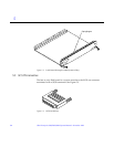
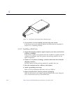
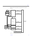
3. Push the board into the card cage, then simultaneously press both
extraction levers to seat the board on the centerplane.
Pushing both levers simultaneously avoids twisting the board and bending
the connector pins, and mates the board centerplane connector to the
matching receptacle on the centerplane. Do not press on board front panel to
seat it—doing so will damage the connector pins.
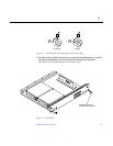
4. Mechanically lock the board to the system chassis by inserting a Phillips
#1 screwdriver into each quarter-turn access slot and then turning to the
locked position.
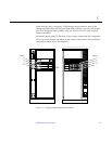
See Figure 5-4 on page 5-7.
5. Replace or connect all necessary cables to the front of the board.
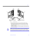
6. Terminate the SCSI out connector if necessary.
The SCSI out connector on Disk boards in a system, which are not daisy
chained to an additional device, must be terminated with a SCSI terminator.
See Figure 5-3 on page 5-4.
Note – The last or only Disk board in a system must have the SCSI out
connector terminated with a fast-wide SCSI terminator, part number 150-2267.
7. Once the board has been installed, a message similar to the following will
be displayed on the monitor (if the system is powered on):
Example depicts screen output when a new Disk board has been hot-
plugged into slot 6 of an operating Enterprise system:
This screen output indicates that the board has been detected by the system
and is in the low power mode. Additionally, any subsequent prtdiag(1M)
output would include information for board slot 6. Again, note that the
system will not use the new board until the system is rebooted.
8. Reboot the system now or schedule a later time to reboot when system
disruption will be minimized.
NOTICE: Disk Board Hotplugged into Slot 6
NOTICE: Board 6 is ready to remove