


Non-Chassis Field Replaceable Units (FRUs) E-7
E
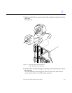
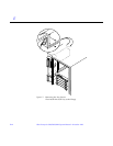
6. Remove the two screws at the bottom of the power sequencer.
7. Tilt the power sequencer slightly so that it clears the top and lift it up and
out of the cabinet.
You may use the power inlet to obtain a grip on the power sequencer.
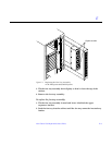
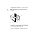
To replace the power sequencer:
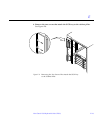
1. Tilt the power sequencer inward and seat the bottom in the cabinet
opening.
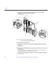
There are two retainers at the bottom of the power sequencer which rest on
the sheet metal at the bottom of the cabinet opening.
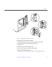
2. Tilt the power sequencer so that it is flush against the cabinet.
3. Replace the two screws at the bottom of the power sequencer.
See Figure E-3.
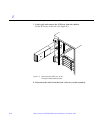
4. Replace the two screws at the top of the power sequencer.
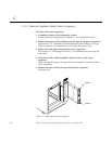
5. Connect all the cable assemblies to the front of the power sequencer.
Reach through the space uncovered by the side panel to replace these cable
assemblies.
6. Replace the side panel closest to the power sequencer.
See Chapter 13, “Preparing for Service,” for information on replacing the
side panel.
7. Replace the power cord assembly at the back of the power sequencer.
See Section E.1.2, “Domestic and International System Cabinet AC Input
Cable Assembly,” for information on replacing the power cord.
8. Power on the Enterprise system.
See the power on instructions in Chapter 12, “Powering Off and On.”
E.1.4 CD Tray Power and Data Cable Assemblies
To remove the cable assembly:
1. Completely power off the Enterprise system.
See the power off instructions in Chapter 12, “Powering Off and On.”