


13-2 Ultra Enterprise 6000/5000/4000 Systems Manual—November 1996
13
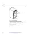
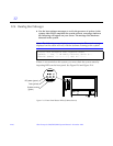
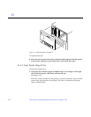
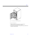
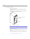
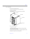
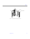
13.3 Internal Access - Enterprise 6000/5000 Systems
The Enterprise 6000/5000 system cabinet panels, shown in Figure 13-1 through
Figure 13-7, consist of the following:
• CD/Tape device door
• Top bezel
• Front panels - hinged door consisting of three vented panels
• Rear screen panel
• Two side panels
• Fan tray screen cover
• Kick panel
• Stabilizer bar
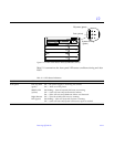
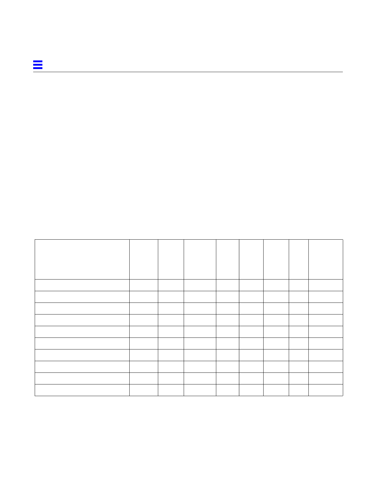
13.3.1 Outer Cover Reference Guide
Use Table 13-1 as a guide to determine which panels to remove to access
replaceable parts for the Enterprise cabinet systems.
Table 13-1 Cover Removal by Assembly
CD/Tape
Device
Door
Top
Bezel
Front
Hinged
Door (3
Vented
Panels)
Rear
Screen
Left
Side
Panel
Right
Side
Panel
Kick
Panel
Fan Tray
Screen
Cover
SCSI Compartment X
Tape Tray or Tape Library X
Fan Tray X
Control Board X
Centerplane X X X
AC power sequencer X
External Cables X X
CPU/Memory Board (Front load) X
I/O or Disk Boards (Rear load) X
Differential SCSI Trays X X