


1-4
Introduction
X6DAT-G/X6DAi-G User's Manual
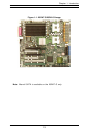
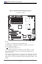
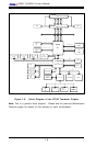
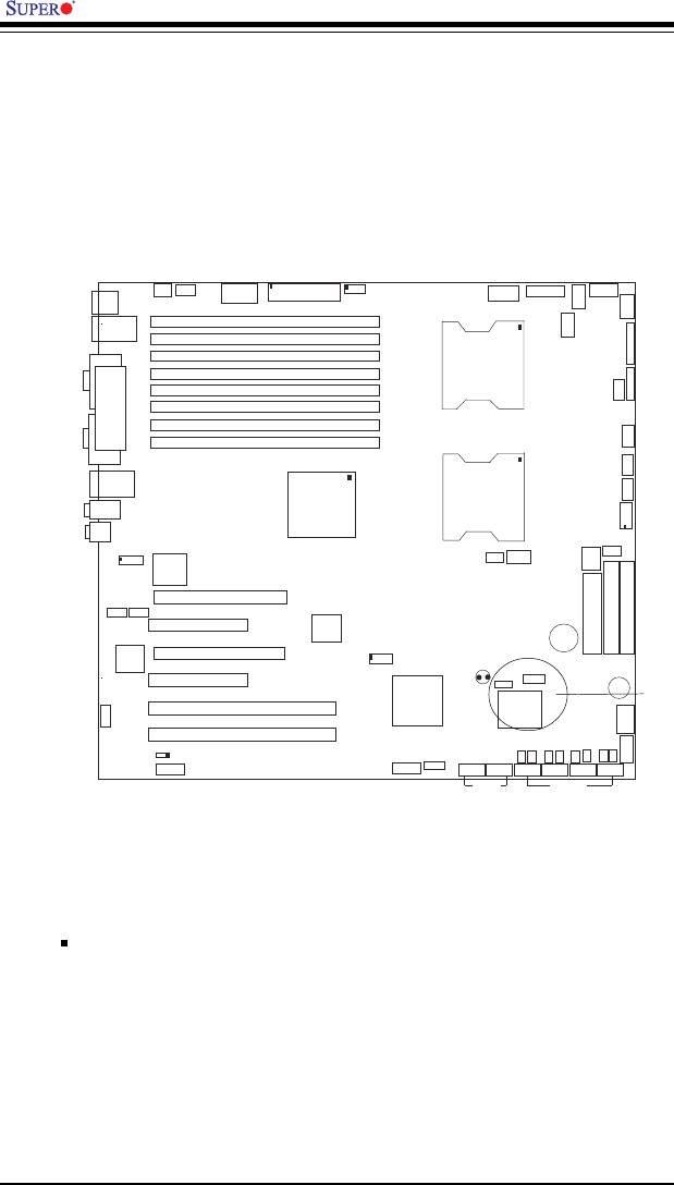
Figure 1-2. X6DAT-G/X6DAi-G Motherboard Layout
(not drawn to scale)
Notes:
1. Jumpers not indicated are for test purposes only.
2. See Chapter 2 for detailed information on jumpers, I/O ports and
JF1 front panel connections.
3. " " indicates the location of Pin 1.
4. The differences between the X6DAT-G and the X6DAi-G: In addi-
tion to the Intel SATA, there are four SATA ports supported by the
Marvell SATA chip.
5. All images and layouts shown in this manual were based upon the latest
PCB revision available at the time of publishing. The motherboard you’ve re-
ceived may or may not look exactly the same as the graphics shown in this
manual.
KB/
Mouse
DIMM 4A
DIMM 4B
DIMM 3A
DIMM 3B
DIMM 2A
DIMM 2B
DIMM 1A
DIMM 1B
SPKR
Tum
water
(NorthBridge)
(South
Bridge)
IDE #1
IDE #2
Floppy
Fan4
USB2/3
JD2
JF
1
FAN7
CPU1
CPU2
JD
1
J24
U
S
B
0/1
JL
A
N
1
CO
M
2
CO
M
1
Parrallel
Port
Fan6
Fan5
J32
4-pin
PWR
Bank 1
Bank 1
Bank 2
Bank 2
Bank 3
Bank 3
Bank 4
Bank 4
ATX PWR
J1B4
JPF
Force
PW
JLAN1
Line_In/
Line_O
ut
JPAC
SI/O
x16 P
C
I E
X
P
#6
P
C
I #5-33M
H
z
P
C
I#3-33M
H
z
P
C
IX
#2-66M
H
z
J2
7
C
D
1
C
D
2
P
C
IX
#1-66M
H
z Z
C
R
GLAN
CTRL
JW
OR
SM
Bus
J
2
2
F
an
3
J
K
1
FAN1
J1D1
JC2
Mic
JC1
x8 P
C
I E
X
P
#4
JW
OL
JL1
J
A
R
JO
H
1
JP
15
JP12
M
arvell
FAN2
JWD
SATA0
SATA1 SATA0
SATA1
SATA2
M
arvell's
SATA3
SATA
ACT
LED
Battery
SATAI
2
C
JPS1
F
an
8
BIOS
JPL1
JB
T
1
6041
6300ESB
JP13
Intel's
D
S
1
D
S
9
D
S
2
D
S
10
D
S
3
D
S
11
D
S
4
D
S
12
J40
J23
X6DAT only