


Chapter 2: Installation
2-7
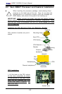
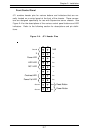
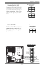
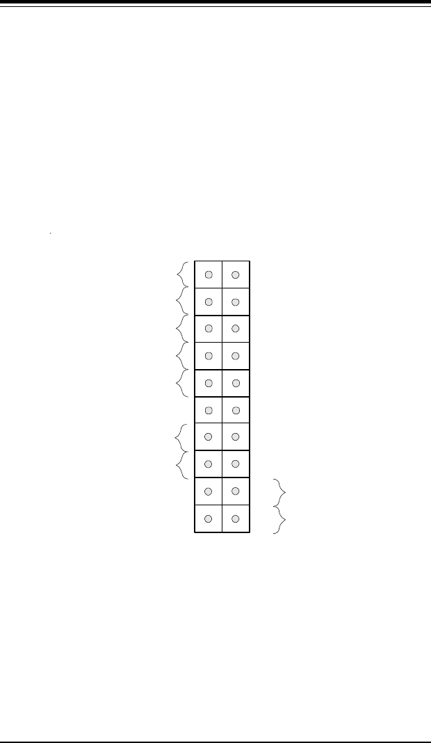
Front Control Panel
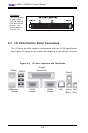
JF1 contains header pins for various buttons and indicators that are nor-
mally located on a control panel at the front of the chassis. These connec-
tors are designed specifically for use with Supermicro server chassis. See
Figure 2-4 for the descriptions of the various control panel buttons and LED
indicators. Refer to the following section for descriptions and pin defini-
tions.
Figure 2-4. JF1 Header Pins
Power Button
Overheat LED
1
NIC1 LED
Reset Button
2
Power Fail LED
HDD LED
Power LED
Reset
Pwr
Vcc
Vcc
Vcc
Vcc
Ground
Ground
1920
Vcc
X
Ground
NMI
X
x
x