


2-12
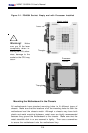
X6DAT-G/X6DAi-G User's Manual
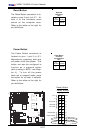
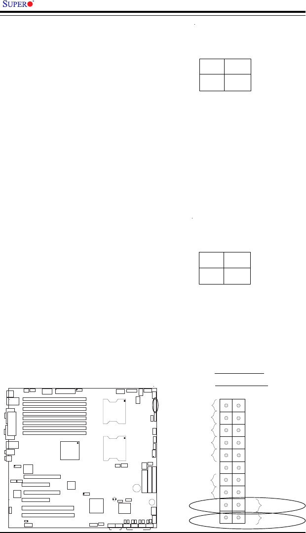
Power Button
Overheat LED
1
NIC1 LED
Reset Button
2
Power Fail LED
HDD LED
Power LED
Reset
Pwr
Vcc
Vcc
Vcc
Vcc
Ground
Ground
1920
Vcc
X
Ground
NMI
X
x
x
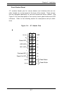
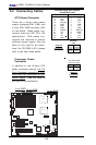
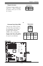
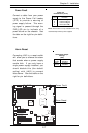
Power Button
The Power Button connection is
located on pins 1 and 2 of JF1.
Momentarily contacting both pins
will power on/off the system. This
button can also be configured to
function as a suspend button
(with a setting in BIOS - see Chap-
ter 4). To turn off the power
when set to suspend mode, press
the button for at least 4 seconds.
Refer to the table on the right for
pin definitions.
Pin
Number
1
2
Definition
PW_ON
Ground
Power Button
Connector
Pin Definitions
(JF1)
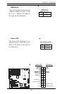
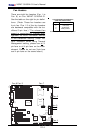
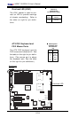
Reset Button
The Reset Button connection is lo-
cated on pins 3 and 4 of JF1. At-
tach it to the hardware reset
switch on the computer case.
Refer to the table on the right for
pin definitions.
Pin
Number
3
4
Definition
Reset
Ground
Reset Pin
Definitions
(JF1)
Reset Button
Power Button
K
B
/
M
o
u
s
e
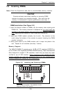
DIMM 4A
DIMM 4B
DIMM 3A
DIMM 3B
DIMM 2A
DIMM 2B
DIMM 1A
DIMM 1B
S
P
K
R
T
u
m
w
a
te
r
(N
o
rth
B
rid
g
e
)
(S
o
u
th
B
rid
g
e
)
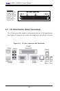
IDE #1
IDE #2
Floppy
F
a
n
4
USB2/3
JD2
J
F
1
FAN7
CPU1
CPU2
JD1
J24
U
S
B
0
/1
J
L
A
N
1
COM2
COM1
Parrallel
Port
Fan6
Fan5
J32
4-pin
PWR
Bank 1
Bank 1
Bank 2
Bank 2
Bank 3
Bank 3
Bank 4
Bank 4
ATX PWR
J1B4
JPF
Force
PW
JLA
N
1
L
in
e
_
In
/
L
in
e
_
O
u
t
JP
A
C
S
I/O
x
1
6
P
C
I E
X
P
#
6
P
C
I #
5
-
3
3
M
H
z
P
C
I#
3
-
3
3
M
H
z
P
C
IX
#
2
-
6
6
M
H
z
J
2
7
C
D
1
C
D
2
P
C
IX
#
1
-
6
6
M
H
z
Z
C
R
G
L
A
N
C
T
R
L
JW
O
R
S
M
B
u
s
J
2
2
Fan
3
JK
1
FAN1
J1D1
JC
2
Mic
JC
1
x
8
P
C
I E
X
P
#
4
JW
O
L
JL1
JAR
JOH1
JP15
JP12
M
a
rve
ll
FAN2
JWD
SATA0
SATA1SATA0
SATA1
SATA2
M
a
rve
ll's
SATA3
S
A
T
A
A
C
T
L
E
D
B
a
tte
ry
SATAI
2
C
JPS1
Fan8
BIOS
J
P
L
1
J
B
T
1
6041
6300ESB
JP13
In
te
l's
D
S
1
D
S
9
D
S
2
D
S
1
0
D
S
3
D
S
1
1
D
S
4
D
S
1
2
J4
0
J23