


Chapter 2: Installation
2-29
K
B
/
M
o
u
s
e
DIMM 4A
DIMM 4B
DIMM 3A
DIMM 3B
DIMM 2A
DIMM 2B
DIMM 1A
DIMM 1B
S
P
K
R
T
u
m
w
a
te
r
(N
o
rth
B
rid
g
e
)
(S
o
u
th
B
rid
g
e
)
IDE #1
IDE #2
Floppy
F
a
n
4
USB2/3
JD2
J
F
1
FAN7
CPU1
CPU2
J
D
1
J24
U
S
B
0
/1
JL
A
N
1
C
O
M
2
C
O
M
1
Parrallel
Port
Fan6
Fan5
J32
4-pin
PWR
Bank 1
Bank 1
Bank 2
Bank 2
Bank 3
Bank 3
Bank 4
Bank 4
ATX PWR
J1B4
JPF
Force
PW
JL
A
N
1
L
in
e
_
In
/
L
in
e
_
O
u
t
JP
A
C
SI/O
x1
6
P
C
I E
X
P
#
6
P
C
I #
5
-3
3
M
H
z
P
C
I#
3
-3
3
M
H
z
P
C
IX
#
2
-6
6
M
H
z
J2
7
C
D
1
C
D
2
P
C
IX
#
1
-6
6
M
H
z
Z
C
R
G
L
A
N
C
T
R
L
J
W
O
R
S
M
B
u
s
J
2
2
F
a
n
3
J
K
1
FAN1
J1D1
JC
2
Mic
JC
1
x
8
P
C
I E
X
P
#
4
J
W
O
L
JL1
JA
R
JO
H
1
JP
1
5
JP12
M
a
rv
e
ll
FAN2
JWD
SATA0
SATA1 SATA0
SATA1
SATA2
M
a
rv
e
ll's
SATA3
S
A
T
A
A
C
T
L
E
D
B
a
tte
ry
SATAI
2
C
JPS1
F
a
n
8
BIOS
J
P
L
1
J
B
T
1
6041
6300ESB
JP13
In
te
l's
D
S
1
D
S
9
D
S
2
D
S
1
0
D
S
3
D
S
1
1
D
S
4
D
S
1
2
J4
0
J2
3
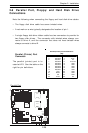
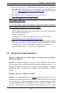
2-8 Parallel Port, Floppy/ and Hard Disk Drive
Connections
Note the following when connecting the floppy and hard disk drive cables:
• The floppy disk drive cable has seven twisted wires.
• A red mark on a wire typically designates the location of pin 1.
• A single floppy disk drive ribbon cable has two connectors to provide for
two floppy disk drives. The connector with twisted wires always con-
nects to drive A, and the connector that does not have twisted wires
always connects to drive B.
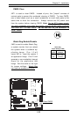
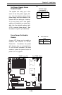
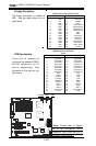
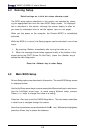
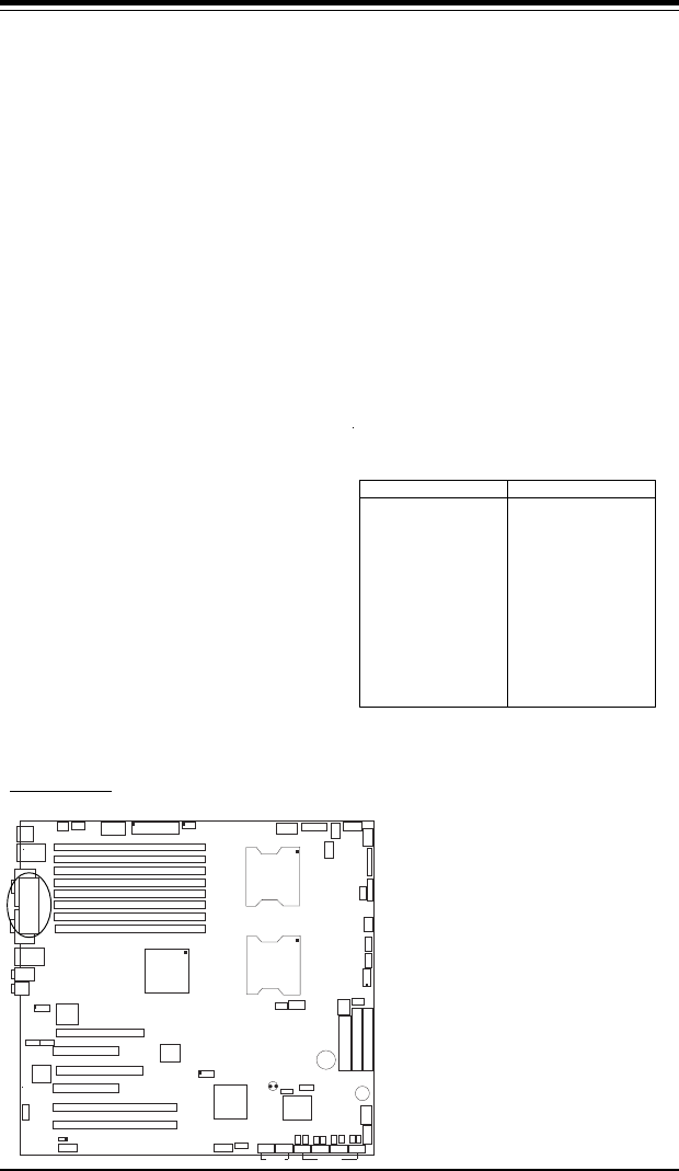
Parallel (Printer) Port
Connector
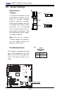
The parallel (printer) port is lo-
cated at J23. See the table on the
right for pin definitions.
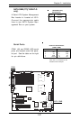
Pin Number Function
1 Strobe-
3 Data Bit 0
5 Data Bit 1
7 Data Bit 2
9 Data Bit 3
11 Data Bit 4
13 Data Bit 5
15 Data Bit 6
17 Data Bit 7
19 ACK
21 BUSY
23 PE
25 SLCT
Pin Number Function
2 Auto Feed
-
4 Error-
6 Init-
8 SLCT IN-
10 GND
12 GND
14 GND
16 GND
18 GND
20 GND
22 GND
24 GND
26 NC
Parallel (Printer) Port Pin Definitions
(J23)
Parallel Port