


2-22
X6DAT-G/X6DAi-G User's Manual
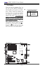
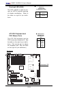
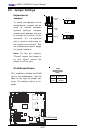
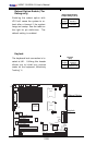
2-6 Jumper Settings
Explanation of
Jumpers
To modify the operation of the
motherboard, jumpers can be
used to choose between
optional settings. Jumpers
create shorts between two pins
to change the function of the
connector. Pin 1 is identified
with a square solder pad on
the printed circuit board. See
the motherboard layout pages
for jumper locations.
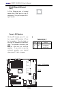
Note: On two pin jumpers,
"Closed" means the jumper is
on and "Open" means the
jumper is off the pins.
Connector
Pins
Jumper
Cap
Setting
Pin 1-2 short
3 2 1
3 2 1
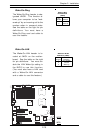
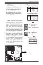
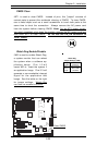
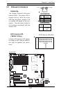
GLAN Enable/Disable
JPL1 enables or disable the GLAN
port on the motherboard. See the
table on the right for jumper set-
tings. The default setting is en-
abled.
Jumper
Position
Pins 1-2
Pins 2-3
Definition
Enabled
Disabled
GLAN
Enable/Disable
Jumper Settings
(JPL1)
K
B
/
M
o
u
s
e
DIMM 4A
DIMM 4B
DIMM 3A
DIMM 3B
DIMM 2A
DIMM 2B
DIMM 1A
DIMM 1B
S
P
K
R
T
u
m
w
a
te
r
(N
o
rth
B
rid
g
e
)
(S
o
u
th
B
rid
g
e
)
IDE #1
IDE #2
F
lo
p
p
y
Fan4
USB2/3
JD2
J
F
1
FAN7
CPU1
CPU2
JD1
J24
USB 0/1
JLAN1
C
O
M
2
C
O
M
1
Parrallel
Port
Fan6
Fan5
J32
4-pin
PWR
Bank 1
Bank 1
Bank 2
Bank 2
Bank 3
Bank 3
Bank 4
Bank 4
ATX PWR
J1B4
JPF
Force
PW
JLAN1
Line_In/
Line_Out
JPAC
SI/O
x16 PCI EXP #6
PCI #5-33MHz
PCI#3-33MHz
PCIX#2-66MHz
J
2
7
C
D
1
C
D
2
PCIX#1-66MHz ZCR
G
L
A
N
C
T
R
L
J
W
O
R
S
M
B
u
s
J
2
2
Fa
n3
JK
1
FAN1
J1D1
JC2
Mic
JC1
x8 PCI EXP #4
J
W
O
L
JL1
J
A
R
J
O
H
1
J
P
1
5
JP12
M
a
rv
e
ll
FAN2
JWD
SATA0
SATA1 SATA0
SATA1
SATA2
M
a
rv
e
ll's
SATA3
SATA
ACT
LED
B
a
tte
ry
SATAI
2
C
JPS1
Fan8
BIOS
J
P
L
1
J
B
T
1
6041
6300ESB
JP13
In
te
l's
D
S
1
D
S
9
D
S
2
D
S
1
0
D
S
3
D
S
1
1
D
S
4
D
S
1
2
J40
J23
GLAN Enable