


Chapter 2: Installation
2-17
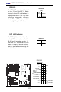
KB/
Mouse
DIMM 4A
DIMM 4B
DIMM 3A
DIMM 3B
DIMM 2A
DIMM 2B
DIMM 1A
DIMM 1B
SPKR
Tumwater
(NorthBridge)
(South
Bridge)
IDE #1
IDE #2
Floppy
F
an
4
USB2/3
JD2
JF
1
FAN7
CPU1
CPU2
JD
1
J24
USB 0/1
JLAN1
C
O
M
2
C
O
M
1
Parrallel
Port
Fan6
Fan5
J32
4-pin
PWR
Bank 1
Bank 1
Bank 2
Bank 2
Bank 3
Bank 3
Bank 4
Bank 4
ATX PWR
J1B4
JPF
Force
PW
JLAN1
Line_In/
Line_Out
JPAC
S
I/O
x16 PCI EXP #6
PCI #5-33MHz
PCI#3-33MHz
PCIX#2-66MHz
J2
7
C
D
1
C
D
2
PCIX#1-66M
Hz ZCR
GLAN
CTRL
JW
OR
SM
Bus
J2
2
Fan3
J
K
1
FAN1
J1D1
JC2
Mic
JC1
x8 PCI EXP #4
JW
OL
JL1
JA
R
JO
H
1
JP
1
5
JP12
Marvell
FAN2
JWD
SATA0
SATA1 SATA0
SATA1
SATA2
Marvell's
SATA3
S
A
T
A
A
C
T
L
E
D
Battery
SATAI
2
C
JPS1
F
a
n
8
BIOS
JPL1
J
B
T
1
6041
6300ESB
JP13
Intel's
D
S
1
D
S
9
D
S
2
D
S
1
0
D
S
3
D
S
1
1
D
S
4
D
S
1
2
J40
J23
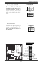
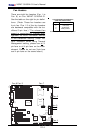
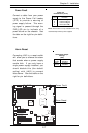
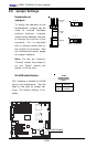
Power Fault
Connect a cable from your power
supply to the Power Fail header
(JP12) to provide a warning of
power supply failure. This warn-
ing signal is passed through the
PWR_LED pin to indicate of a
power failure on the chassis. See
the table on the right for pin defini-
tions.
Power Fail
Pin Definitions (JP12)
Pin
Number
1
2
3
4
Definition
P/S 1 Fail Signal
P/S 2 Fail Signal
P/S 3 Fail Signal
Reset (from MB)
Note: This feature is only available when using
redundant Supermicro power supplies.
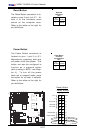
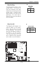
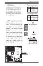
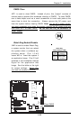
Alarm Reset
Connecting JAR to a reset switch
will allow you to silence the alarm
that sounds when a power supply
module fails. If you only have a
single power supply installed, you
should disable this (the default
setting) with (JAR) to prevent
false alarms. See the table on the
right for pin definitions.
Jumper
Position
Open
Closed
Definition
Enabled
Disabled
Alarm Reset Jumper
Settings
(JAR)
Power Fault
Alarm Reset