


2-14
X6DAT-G/X6DAi-G User's Manual
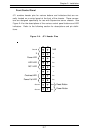
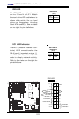
KB/
Mouse
DIMM 4A
DIMM 4B
DIMM 3A
DIMM 3B
DIMM 2A
DIMM 2B
DIMM 1A
DIMM 1B
SPKR
Tumwater
(NorthBridge)
(South
Bridge)
IDE #1
IDE #2
Floppy
F
an
4
USB2/3
JD2
J
F
1
FAN7
CPU1
CPU2
JD
1
J24
USB 0/1
JLAN1
C
O
M
2
C
O
M
1
Parrallel
Port
Fan6
Fan5
J32
4-pin
PWR
Bank 1
Bank 1
Bank 2
Bank 2
Bank 3
Bank 3
Bank 4
Bank 4
ATX PWR
J1B4
JPF
Force
PW
JLAN1
Line_In/
Line_Out
JPAC
S
I/O
x16 PCI EXP #6
PCI #5-33MHz
PCI#3-33MHz
PCIX#2-66MHz
J
2
7
C
D
1
C
D
2
PCIX#1-66M
Hz ZCR
GLAN
CTRL
JW
OR
SM
Bus
J
2
2
Fan3
J
K
1
FAN1
J1D1
JC2
Mic
JC1
x8 PCI EXP #4
JW
OL
JL1
JA
R
JO
H
1
JP
1
5
JP12
Marvell
FAN2
JWD
SATA0
SATA1 SATA0
SATA1
SATA2
Marvell's
SATA3
S
A
T
A
A
C
T
L
E
D
Battery
SATAI
2
C
JPS1
F
a
n
8
BIOS
JPL1
J
B
T
1
6041
6300ESB
JP13
Intel's
D
S
1
D
S
9
D
S
2
D
S
1
0
D
S
3
D
S
1
1
D
S
4
D
S
1
2
J40
J23
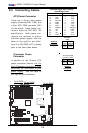
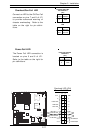
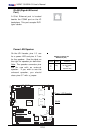
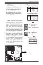
Fan Headers
There are eight fan headers (Fan 1 to
Fan 8) on the X6DAT-G/X6DAi-G.
See the table on the right for pin defini-
tions. (*Note: These fan headers are
4-pin fan. Pins 1-3 of the fan headers
are backward compatible with the tra-
ditional 3-pin fans.) *The onboard fan
speed is controlled by Thermal Man-
agement via BIOS--Hardware Monitor
in the Advanced Setting. (Note: De-
fault: Disabled. When using Thermal
Management setting, please use all 3-
pin fans or all 4-pin fans on the moth-
erboard. Please do not use 3-pin fans
and 4-pin fans on the same board.)
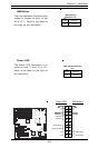
4-pin Fan Header Pin Definitions
(CPU and Chassis Fans )
Pin#
1
2
3
Definition
Ground (black)
+12V (red)
Tachometer
Caution: These fan headers use DC power.
4 PWR_Control
Fan 6
Fan 5
Fan 7
Fan 1
Fan 2
Fan 3
Fan 8
Fan 4