


2-26
X6DAT-G/X6DAi-G User's Manual
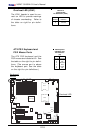
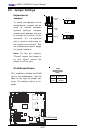
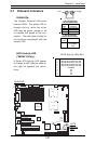
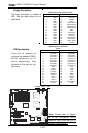
Reboot Option Enable (*For
Debug only)
Enabling the reboot option with
JP15 will cause the system to re-
boot after a timeout if the system
hangs on bootup. See the table on
the right for pin definitions. The
default setting is enabled.
Jumper
Position
Open
Closed
Definition
Enabled
Disabled
Reboot Option Enable
Jumper Settings (JP15)
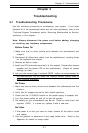
K
B
/
M
o
use
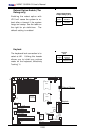
DIMM 4A
DIMM 4B
DIMM 3A
DIMM 3B
DIMM 2A
DIMM 2B
DIMM 1A
DIMM 1B
SP
K
R
Tum
w
ater
(N
orthBridge)
(S
outh
B
ridge)
IDE #1
IDE #2
Floppy
Fan4
USB2/3
JD2
J
F
1
FAN7
CPU1
CPU2
JD1
J24
U
SB 0/1
JLAN1
C
O
M
2
C
O
M
1
Parrallel
Port
Fan6
Fan5
J32
4-pin
PWR
Bank 1
Bank 1
Bank 2
Bank 2
Bank 3
Bank 3
Bank 4
Bank 4
ATX PWR
J1B4
JPF
Force
PW
JLAN1
Line_In/
Line_O
ut
JPAC
SI/O
x16 PC
I EXP #6
PC
I #5-33M
H
z
PC
I#3-33M
H
z
PC
IX#2-66M
H
z
J2
7
C
D
1
C
D
2
PC
IX#1-66M
H
z ZC
R
G
LA
N
C
TR
L
JW
O
R
SM
B
us
J2
2
F
a
n
3
JK
1
FAN1
J1D1
JC2
Mic
JC1
x8 P
C
I EX
P #4
JW
O
L
JL1
JAR
JOH1
JP15
JP12
M
arvell
FAN2
JWD
SATA0
SATA1 SATA0
SATA1
SATA2
M
arvell's
SATA3
SATA
ACT
LED
B
attery
SATAI
2
C
JPS1
Fan8
BIOS
JP
L1
J
B
T
1
6041
6300ESB
JP13
Intel's
D
S
1
D
S
9
D
S
2
D
S
1
0
D
S
3
D
S
1
1
D
S
4
D
S
1
2
J40
J23
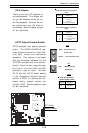
Reboot Option
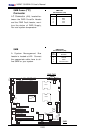
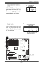
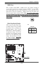
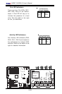
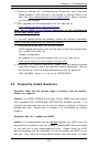
Keylock
Keylock
The keyboard lock connection is lo-
cated at JK1. Utilizing this header
allows you to inhibit any actions
made on the keyboard, effectively
"locking" it.
Jumper
Position
1
2
Definition
Ground
Keylock R-N
Keylock
(JK1)