


Chapter 2: Installation
2-15
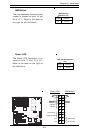
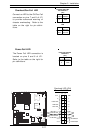
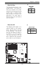
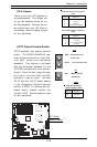
Wake-On-Ring
The Wake-On-Ring header is des-
ignated JWOR. This function al-
lows your computer to be "wak-
ened-up" by an incoming call to the
modem when in suspend state.
See the table on the right for pin
definitions. You must have a
Wake-On-Ring card and cable to
use this feature.
Wake-on-Ring
Pin Definitions
(JWOR)
Pin
Number
1
2
Definition
Ground
Wake-up
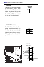
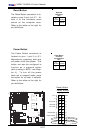
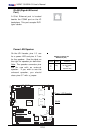
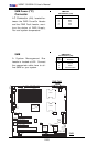
Wake-On-LAN
The Wake-On-LAN header is lo-
cated at JWOL on the mother-
board. See the table on the right
for pin definitions. You must en-
able the LAN Wake-Up setting in
the BIOS to use this function.
(You must also have a LAN card
with a Wake-On-LAN connector
and a cable to use this feature.)
Pin
Number
1
2
3
Definition
+5V Standby
Ground
Wake-up
Wake-On-LAN Pin
Definitions (JWOL)
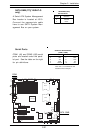
WOR
WOL
KB/
Mouse
DIMM 4A
DIMM 4B
DIMM 3A
DIMM 3B
DIMM 2A
DIMM 2B
DIMM 1A
DIMM 1B
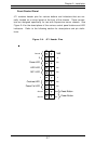
SPKR
Tumwater
(NorthBridge)
(South
Bridge)
IDE #1
IDE #2
Floppy
F
an
4
USB2/3
JD2
JF
1
FAN7
CPU1
CPU2
JD
1
J24
USB 0/1
JLAN1
C
O
M
2
C
O
M
1
Parrallel
Port
Fan6
Fan5
J32
4-pin
PWR
Bank 1
Bank 1
Bank 2
Bank 2
Bank 3
Bank 3
Bank 4
Bank 4
ATX PWR
J1B4
JPF
Force
PW
JLAN1
Line_In/
Line_Out
JPAC
S
I/O
x16 PCI EXP #6
PCI #5-33MHz
PCI#3-33MHz
PCIX#2-66MHz
J2
7
C
D
1
C
D
2
PCIX#1-66M
Hz ZCR
GLAN
CTRL
JW
OR
SM
Bus
J2
2
Fan3
JK
1
FAN1
J1D1
JC2
Mic
JC1
x8 PCI EXP #4
JW
OL
JL1
JA
R
JO
H
1
JP
1
5
JP12
Marvell
FAN2
JWD
SATA0
SATA1 SATA0
SATA1
SATA2
Marvell's
SATA3
S
A
T
A
A
C
T
L
E
D
Battery
SATAI
2
C
JPS1
F
a
n
8
BIOS
JPL1
J
B
T
1
6041
6300ESB
JP13
Intel's
D
S
1
D
S
9
D
S
2
D
S
1
0
D
S
3
D
S
1
1
D
S
4
D
S
1
2
J40
J23