


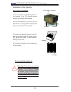
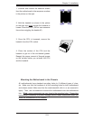

Chapter 2: Installation
2-11
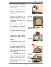
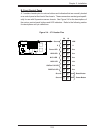
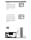
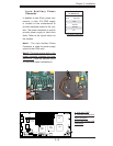
NIC1/NIC2 LED Indicators
The NIC (Network Interface Control-
ler) LED connection for GLAN port1 is
located on pins 11 and 12 of JF1 and
the LED connection for GLAN Port2
is on Pins 9 and 10. Attach the NIC
LED cables to display network activity.
Refer to the table on the right for pin
defi nitions.
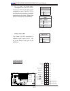
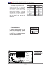
HDD LED
The HDD LED connection is located
on pins 13 and 14 of JF1. Attach the
hard drive LED cable here to display
disk activity (for any hard drives on
the system, including Serial ATA).
See the table on the right for pin
defi nitions.
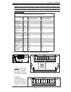
HDD LED
Pin Defi nitions (JF1)
Pin# Defi nition
13 +5V
14 HD Active
GLAN1/2 LED
Pin Defi nitions (JF1)
Pin# Defi nition
9/11 Vcc
10/12 Ground
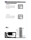
A
B
C
A. HDD LED
B. NIC1 LED
C. NIC2 LED
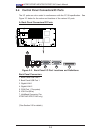
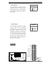
Power Button
OH/Fan Fail LED
1
NIC1 LED
Reset Button
2
HDD LED
Power LED
Reset
PWR
Vcc
Vcc
Vcc
Vcc
Ground
Ground
1920
Vcc
X
Ground
NMI
X
Vcc
PWR Fail LED
NIC2 LED
S
UPER X7DBT
LAN1
®
LAN2
Fan1/2
FP CTRL
SMB
Battery
North
Brid
ge
VGA
Infini-
U
SB0
/1
JPG1
South
Bridge
DIMM 1A
(
Bank 1)
JPL2
PCI-E x8
DIMM 1B (Ban
k
1)
DIMM 2A
(
Ban
k
2
)
DI
MM 2B (
Ban
k
2
)
DIMM 3A
(
Ban
k
3)
DIMM 3B
(
Ban
k
3)
DIMM
4
A
(
Ban
k
4)
DI
MM 4
B
(
Ban
k
4)
JBT1
JWOR
JWO
L
LAN
CTRL
SIMS0
L
E3
COM2
JPL1
SATA
3
J
I
2
C1
JI
2
C2
J7
JP1
JOH1
J
L1
4
-Pin
P
WR
BIOS
Buzzer
U
SB2/
3
CPU1
Fan
3
/
4
Fan
5
/
6
L
E
1
VGA
CTRL
S I/O
L
E
2
Band
INF
Ctrl
Video
Memory
J
1
SATA2
SATA
0
SATA1
CPU2
Fan
7
/
8
20-
Pi
n P
W
R
2
0-
PinPWR
SG
PI
O
WD