


2-16
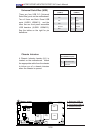
X7DBT/X7DBT-INF/X7DGT/X7DGT-INF User's Manual
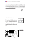
S
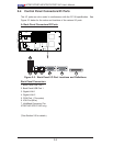
UPER X7DBT
LAN1
®
LAN2
Fan1/2
FP CTRL
SMB
Battery
North
Bridge
VGA
Infini-
USB0/1
JPG1
South
Bridge
D
I
MM 1A
(Bank 1)
JPL2
PCI-E x8
DIMM 1B
(Bank
1)
DIMM 2A (Bank
2)
DIMM 2B
(Bank
2)
DIMM 3A (Bank
3)
DIMM 3B (Bank
3)
DIMM
4
A
(Bank
4)
D
I
MM 4B (Bank 4)
JBT1
JWO
R
JWOL
LAN
CTRL
SIMS0
L
E3
COM2
JPL1
SATA3
JI
2
C1
JI
2
C2
J7
JP1
JOH
1
JL1
4-
P
in
PW
R
BIOS
Buzzer
USB2/3
CPU1
Fan3
/4
Fan5
/6
L
E
1
VGA
CTRL
S I/O
L
E
2
Band
INF
Ctrl
Video
Memory
J1
SATA2
SATA0
SATA1
CPU2
Fan7
/8
2
0-P
i
n PWR
20-P
i
nP
W
R
S
GPI
O
WD
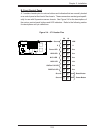
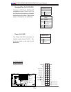
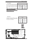
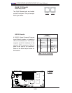
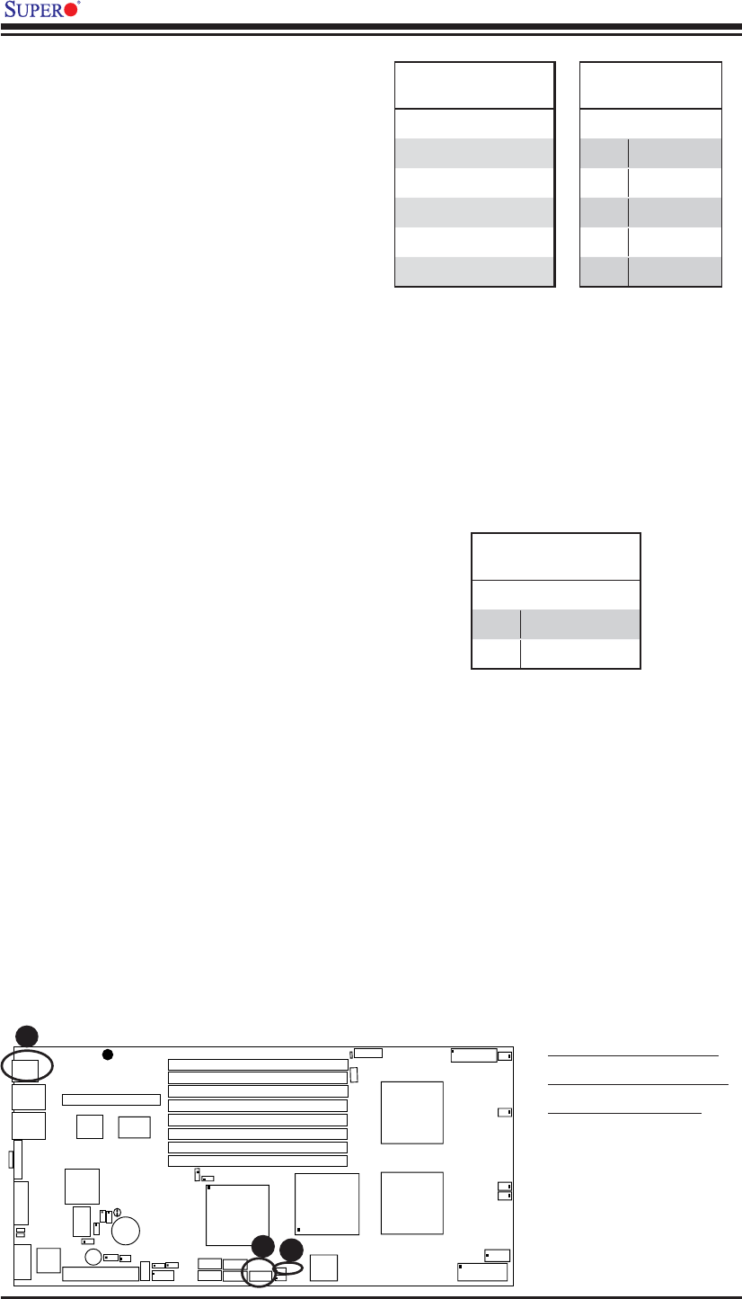
Universal Serial Bus (USB)
There are four USB 2.0 (Universal
Serial Bus) ports on the motherboard.
Two of them are Back Panel USB
ports (JUSB1: USB#0/1), and the
other two are front panel accessible
USB headers (JUSB2: USB#2/3).
See the tables on the right for pin
defi nitions.
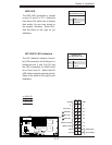
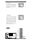
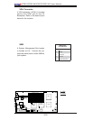
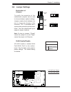
Chassis Intrusion
A Chassis Intrusion header (JL1) is
located on the motherboard. Attach
the appropriate cable from the chassis
to inform you of a chassis intrusion
when the chassis is opened.
Chassis Intrusion
Pin Defi nitions (JL1)
Pin# Defi nition
1 Intrusion Input
2 Ground
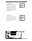
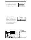
A
B
C
A. Backpanel USB 0-1
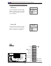
B. Front Panel USB 2-3
C. Chassis Intrusion
Back Panel USB
(USB0/1)
Pin# Defi nitions
1 +5V
2PO-
3PO+
4 Ground
5N/A
Front Panel USB
(USB2/3)
Pin# Defi nition
1 Vcc
2 Data-
3 Data+
4 Ground
5NA