


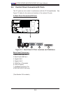
Chapter 2: Installation
2-15
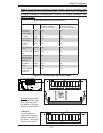
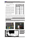
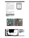
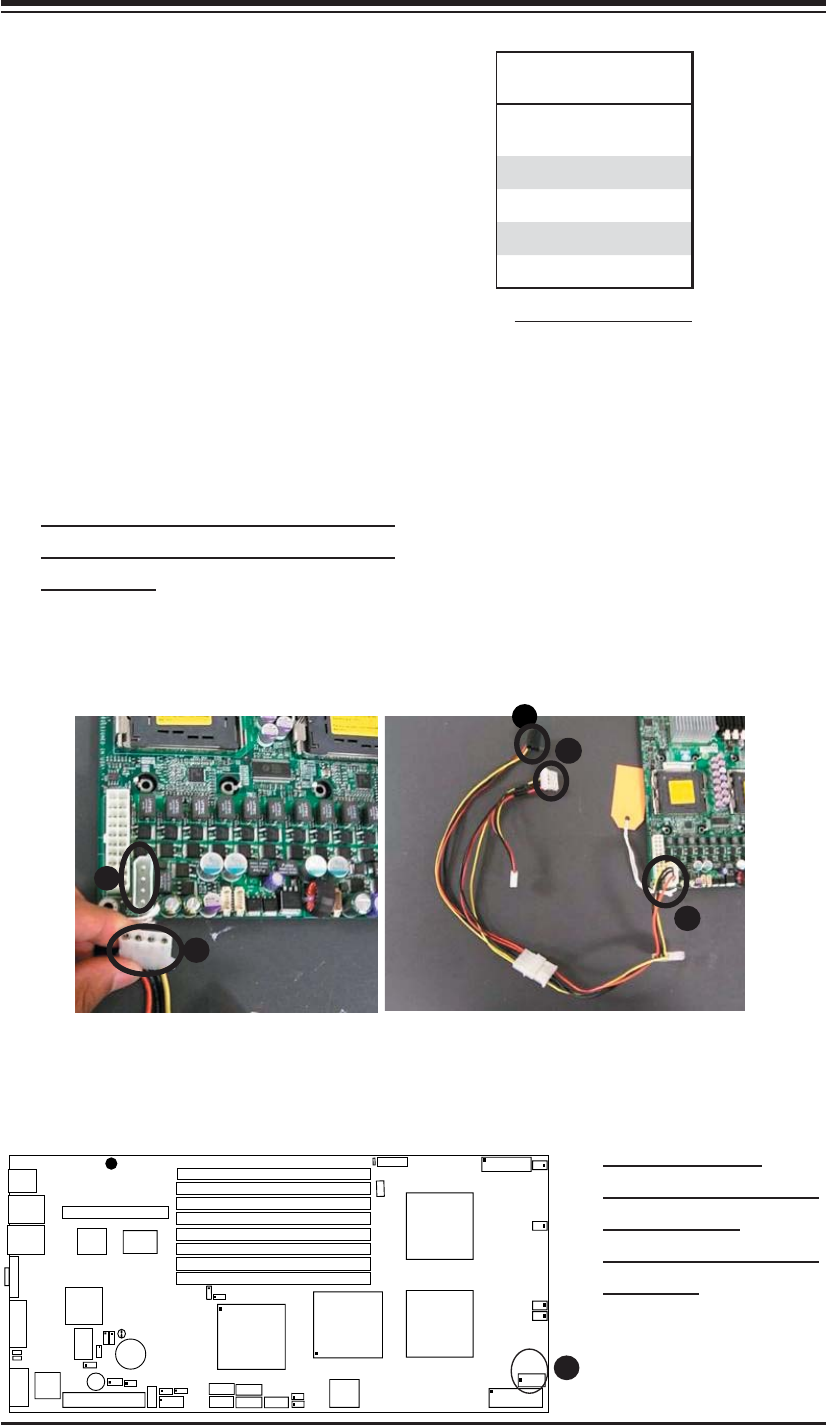
Required Connection
D
4-pin Auxiliary Power
Connector
In addition to two 20-pin power con-
nectors, a 4-pin 12V PWR supply
is located on the motherboard to
provide adequate power to the sys-
tem. This power connector is used to
provide power supply to hard drive
disks. Refer to the layout below for
the location.
Note1 : The 4-pin Auxiliary Power
Connector is used for power supply
output to the HDDs only.
Note 2: The black square (dot) on the
power connector indicates the loca-
tion of Pin 1. (See the pictures below
for the power cable connections.)
S
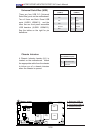
UPER X7DBT
LAN1
®
LAN2
Fan1/2
FP CTRL
SMB
Battery
N
orth
Brid
ge
VGA
Infini-
USB0/1
JPG1
Sout
h
Brid
ge
D
IMM 1A (
Bank 1
)
J
PL2
PCI-E x8
D
IMM 1B (
Ban
k 1
)
D
IMM 2A
(
Bank
2
)
D
IMM 2B (
Bank 2)
D
I
MM
3
A (
Bank 3)
D
IMM 3B (
Bank 3)
D
IMM 4A (Bank 4)
D
IMM 4
B
(
Bank
4)
JBT1
JWOR
JWOL
J29
LAN
CTRL
J
USB1
SIMS0
LE3
COM2
JPL1
J
PCE1
SATA3
JI
2
C1
JI
2
C2
J7
JP1
JOH
1
J18
JVGA1
JL1
4-Pin
P
W
R
BIOS
Buzz
er
SP1
U
SB2/3
J
U
SB2
CPU1
JF1
Fan3/4
Fan5/6
L
E
1
VG
A
CTRL
S I/O
L
E2
JCOM2
Band
INF
Ctrl
Video
Memory
J7
B1
J7
B2
J7
B
3
J8
B1
J8
B2
J8
B
3
J9
B1
J9
B2
J1
SATA2
SATA0
SATA1
CPU2
Fan
7
/8
20-Pin PW
R
20-PinP
WR
J17
J
P10
S
GPIO
WD
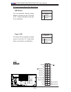
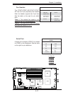
A. 4-pin Aux. PWR
B. One Male (Receptacle)
PWR Connector
C.& D. Two Female PWR
Connectors
A
A
B
B
C
4-Pin Power
Pin Defi nitions
Pin # Defi nition
1 +12V
2 Ground
3 Ground
5 +5V