


Chapter 2: Installation
2-23
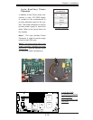
S
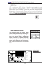
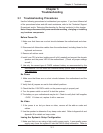
UPER X7DBT
LAN1
®
LAN2
Fan1/2
FP CTRL
SMB
Battery
N
ort
h
Bridge
VGA
Infini-
USB0/1
JPG1
South
Bridge
DIMM 1A (Bank
1)
JPL2
PCI-E x8
D
I
MM 1B
(Bank 1)
DIMM 2A
(Bank
2)
D
I
MM 2B
(Bank 2)
DIMM
3
A
(Bank
3)
DIMM 3B (Bank
3)
D
I
MM
4A (Bank 4)
DIMM 4B (Bank
4)
JBT1
JWOR
JWOL
LAN
CTRL
SIMS0
L
E3
COM2
JPL1
SATA3
J
I
2
C1
JI
2
C2
J7
JP1
JOH1
JL1
4-
P
in
P
WR
BIOS
Buzz
er
USB2/3
CPU1
Fan3
/4
Fan5
/6
L
E
1
VGA
CTRL
S I/O
L
E2
Band
I
NF
Ctrl
Video
Memory
J
1
SATA2
SATA0
SATA1
CPU2
Fan7/8
20-Pi
n PWR
20-P
inP
W
R
S
GPI
O
WD
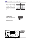
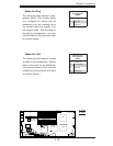
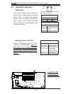
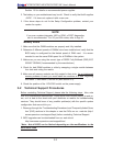
VGA Enable/Disable
Jumper Settings
Both Jumpers Defi nition
Pins 1-2 Enabled
Pins 2-3 Disabled
A
B
A. VGA Enabled
B. I
2
C Bus to PCI slots
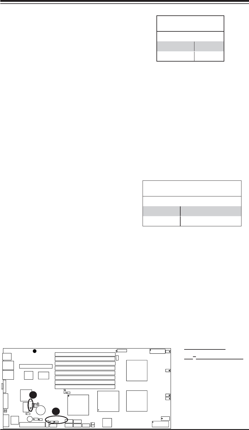
VGA Enable/Disable
JPG1 allows you to enable or disable the
VGA port. The default position is on pins
1 and 2 to enable VGA. See the table
on the right for jumper settings.
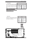
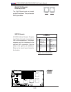
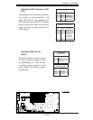
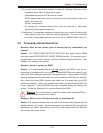
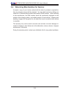
I
2
C Bus to the PCI-E Slot
JI
2
C1/JI
2
C2 allows you to enable the
I
2
C Bus to communicate with the PCI-
Express slot. For the jumpers to work
properly, please set both jumpers to the
same setting. If enabled, both jumpers
must be enabled. If disabled, both
jumpers must be disabled. See the table
on the right for jumper settings.
I
2
C to PCI-Exp Slot
Jumper Settings
Jumper Setting Defi nition
Closed Enabled
Open Disabled (*Default)