


Chapter 2: Installation
2-17
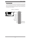
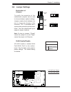
S
UPER X7DBT
LAN1
®
LAN2
Fan1/2
FP CTRL
SMB
Battery
North
Bridge
VGA
Infini-
USB
0/1
JPG1
Sout
h
Bridge
D
I
MM 1A (Bank 1)
JPL2
PCI-E x8
DIMM 1B
(Bank 1
)
D
IMM 2A (Bank 2
)
DIMM 2B
(Bank 2
)
DIMM 3A (Bank 3)
D
IMM 3B (
Ban
k 3)
DIMM 4A (Bank 4)
DIMM 4B (Bank 4)
JBT1
JWOR
JWOL
LAN
CTRL
SIMS0
LE3
COM2
JPL1
SATA3
JI
2
C1
JI
2
C2
J7
JP1
JOH1
JL1
4-Pin
PWR
BIOS
B
uzz
er
U
SB2/
3
CPU1
Fan
3/
4
Fan5/6
LE
1
VGA
CTRL
S I/O
L
E
2
Band
I
NF
Ctr
l
Video
Memory
J1
SATA2
SATA0
SATA1
CPU2
Fan
7/
8
20-Pin PW
R
20-Pi
nP
WR
SGPIO
WD
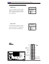
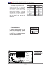
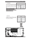
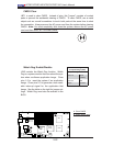
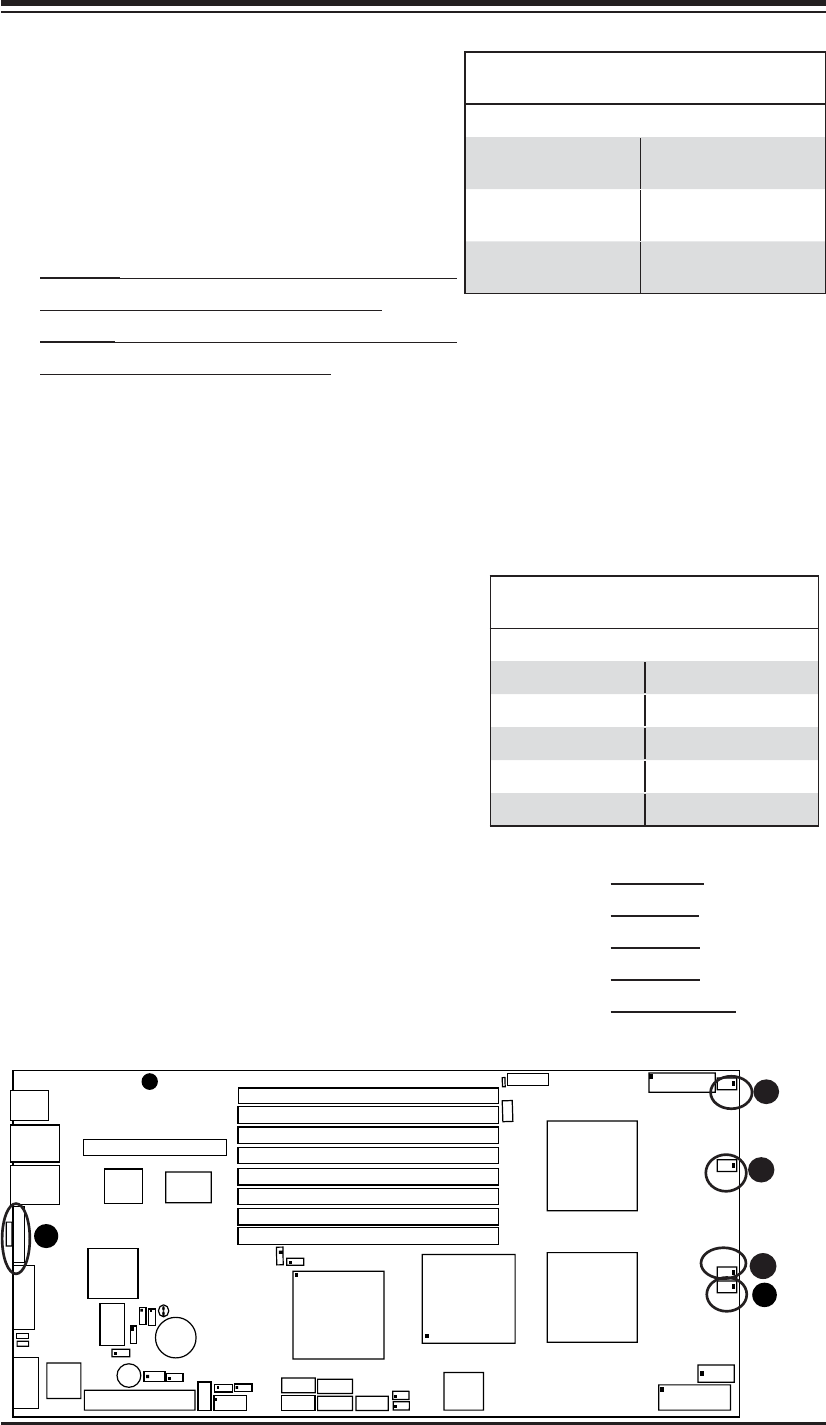
Fan Headers
The X7DBT/X7DBT-INF/X7DGT/X7DGT-
INF has four 6-pin proprietary fan headers.
Each fan header supports two 3-pin fans.
See the table on the right for pin defi ni-
tions.
*Note 1: The onboard fan speed is con-
trolled by the CPU die temperature.
*Note 2: The white dot on each fan header
indicates the location of Pin 1.
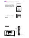
B
C
E
D
A
A. Fans 12
B. Fan 3/4
C. Fan 5/6
D. Fan 7/8
E. COM 2 Port
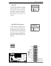
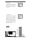
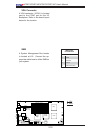
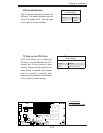
Serial Port
A serial port connector (COM 2) is located
at JCOM2 on the Backpanel. See the table
on the right for pin defi nitions.
Serial Port Pin Defi nitions
(COM2)
Pin # Defi nition Pin # Defi nition
1 CD 6 DSR
2RD 7RTS
3TD 8CTS
4 DTR 9 RI
5 Ground 10 NC
Fan Header Pin Defi nitions
Pin # Defi nition Pin # Defi nition
1 PWR (DC
Speed CTRL)
4 Ground
2 Tachometer for
Fan 1,3 or 5
5 Tachometer for
Fan 2,4 or 6
3 Ground 6 PWR (DC
Speed CTRL)