


Chapter 2: Installation
2-21
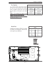
S
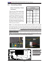
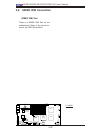
UPER X7DBT
LAN1
®
LAN2
Fan1/2
FP CTRL
SMB
Battery
N
ort
h
Bridge
VGA
Infini-
USB0/1
JPG1
South
Bridge
DIMM 1A (Bank
1)
JPL2
PCI-E x8
D
I
MM 1B
(Bank 1)
DIMM 2A
(Bank
2)
D
I
MM 2B (Bank 2)
DIMM
3
A
(Bank
3)
DIMM 3B (Bank
3)
D
I
MM
4
A (Bank 4)
DIMM 4B (Bank
4)
JBT1
JWOR
JWOL
LAN
CTRL
SIMS0
L
E3
COM2
JPL1
SATA3
J
I
2
C1
JI
2
C2
J7
JP1
JOH1
JL1
4-
P
in
P
WR
BIOS
Buzz
er
USB2/3
CPU1
Fan3
/4
Fan5
/6
L
E
1
VGA
CTRL
S I/O
L
E2
Band
I
NF
Ctrl
Video
Memory
J
1
SATA2
SATA0
SATA1
CPU2
Fan7
/8
20-Pi
n PWR
20-P
inP
W
R
S
GPI
O
WD
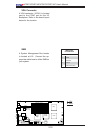
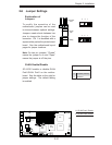
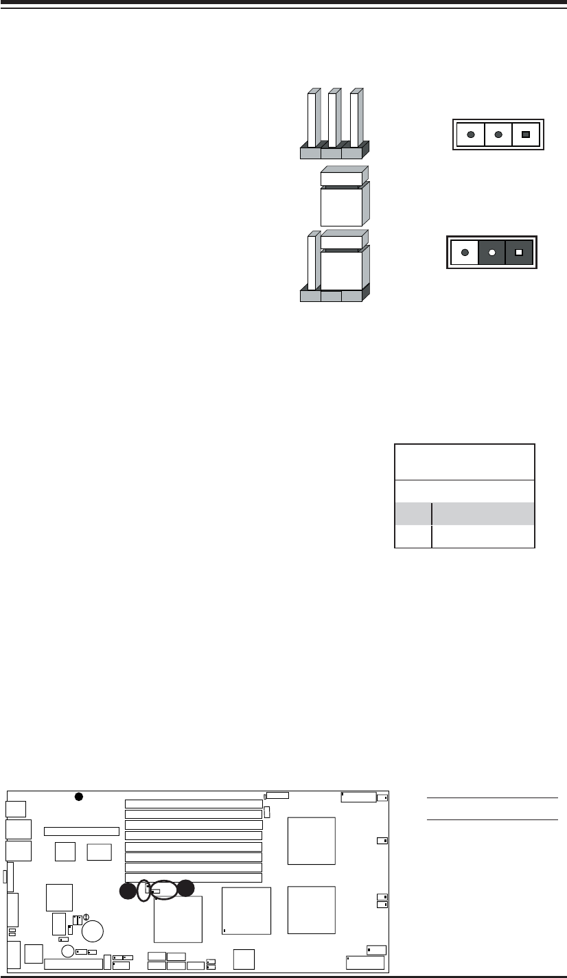
2-6 Jumper Settings
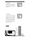
Explanation of
Jumpers
To modify the operation of the
motherboard, jumpers can be used
to choose between optional settings.
Jumpers create shorts between two
pins to change the function of the
connector. Pin 1 is identifi ed with a
square solder pad on the printed circuit
board. See the motherboard layout
pages for jumper locations.
Note: On two pin jumpers, "Closed"
means the jumper is on and "Open"
means the jumper is off the pins.
Connector
Pins
Jumper
Cap
Setting
Pin 1-2 short
3 2 1
3 2 1
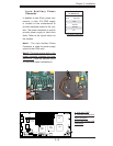
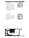
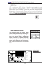
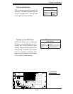
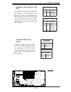
GLAN Enable/Disable
JPL1/JPL2 enable or disable GLAN
Port1/GLAN Port2 on the mother-
board. See the table on the right for
jumper settings. The default setting
is enabled.
GLAN Enable
Pin# Defi nition
1-2 Enabled (*default)
2-3 Disabled
A
A. GLAN Port1 Enable
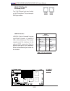
B. GLAN Port2 Enable
B