


Chapter 2: Installation
2-13
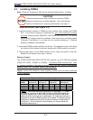
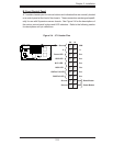
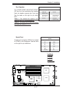
Power Button
OH/Fan Fail LED
1
NIC1 LED
Reset Button
2
HDD LED
Power LED
Reset
PWR
Vcc
Vcc
Vcc
Vcc
Ground
Ground
1920
Vcc
X
Ground
NMI
X
Vcc
PWR Fail LED
NIC2 LED
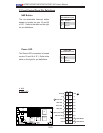
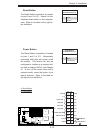
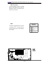
Power Button
The Power Button connection is located
on pins 1 and 2 of JF1. Momentarily
contacting both pins will power on/off
the system. This button can also be
confi gured to function as a suspend but-
ton (with a setting in BIOS - see Chapter
4). To turn off the power when set to
suspend mode, press the button for at
least 4 seconds. Refer to the table on
the right for pin defi nitions.
Power Button
Pin Defi nitions (JF1)
Pin# Defi nition
1 Signal
2 +3V Standby
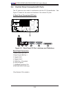
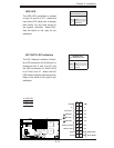
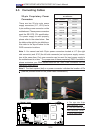
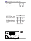
A. Reset Button
B. PWR Button
B
A
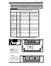
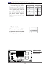
S
UPER X7DBT
LAN1
®
LAN2
Fan1/2
FP CTRL
SMB
Battery
North
Brid
ge
VGA
Infini-
U
SB0/1
JPG1
South
Brid
ge
DIMM 1A
(
Ban
k
1
)
JPL2
PCI-E x8
DIMM 1B
(
Bank 1)
DI
MM 2A (
Ban
k
2
)
D
IMM 2B (
Ban
k
2)
DIMM 3A
(Ban
k
3)
DIMM 3B
(
Ban
k
3)
DI
MM 4
A
(
Ban
k
4)
DIMM 4B
(
Ban
k
4)
JBT1
JWOR
JWO
L
LAN
CTRL
SIMS0
L
E3
COM2
JPL1
SATA
3
J
I
2
C1
JI
2
C2
J7
JP1
JOH1
J
L1
4
-Pin
P
W
R
BIOS
B
uzzer
U
SB2/
3
CPU1
Fan
3
/
4
Fan
5
/
6
L
E
1
VGA
CTRL
S I/O
L
E
2
Band
INF
Ctrl
Video
Memory
J
1
SATA2
SATA
0
SATA1
CPU2
Fan
7
/
8
20-
Pi
n P
W
R
2
0-
P
inPWR
SG
PI
O
WD
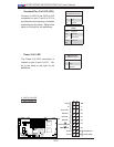
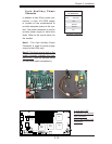
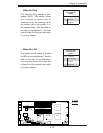
Reset Button
The Reset Button connection is located
on pins 3 and 4 of JF1. Attach it to the
hardware reset switch on the computer
case. Refer to the table on the right for
pin defi nitions.
Reset Button
Pin Defi nitions (JF1)
Pin# Defi nition
3 Reset
4 Ground