


Chapter 2: Installation
2-25
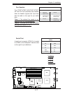
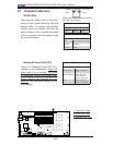
S
UPER X7DBT
LAN1
®
LAN2
Fan1/2
FP CTRL
SMB
Battery
N
ort
h
Bridge
VGA
Infini-
USB0/1
JPG1
South
Bridge
DIMM 1A (Bank
1)
JPL2
PCI-E x8
D
I
MM 1B
(Bank 1)
DIMM 2A
(Bank
2)
D
I
MM 2B (Bank 2)
DIMM
3
A
(Bank
3)
DIMM 3B (Bank
3)
D
I
MM
4
A (Bank 4)
DIMM 4B (Bank
4)
JBT1
JWOR
JWOL
LAN
CTRL
SIMS0
L
E3
COM2
JPL1
SATA3
J
I
2
C1
JI
2
C2
J7
JP1
JOH1
JL1
4-
P
in
P
WR
BIOS
Buzz
er
USB2/3
CPU1
Fan3
/4
Fan5
/6
L
E
1
VGA
CTRL
S I/O
L
E2
Band
I
NF
Ctrl
Video
Memory
J
1
SATA2
SATA0
SATA1
CPU2
Fan7
/8
20-Pi
n PWR
20-P
inP
W
R
S
GPI
O
WD
B
A
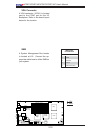
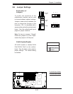
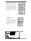
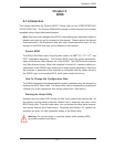
A. OH LED
Overheat LED/Fan Fail
(JOH1)
The JOH1 header is used to connect
an LED to provide warnings of chas-
sis overheating. This LED will blink
to indicate system overheat or a fan
failure. Refer to the table on right for
pin defi nitions.
Overheat LED
Pin Defi nitions
Pin# Defi nition
1 5vDC
2 OH Active
OH/Fan Fail LED
State Message
Solid Overheat
Blinking Fan Fail
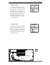
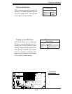
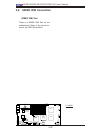
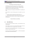
Infi niBand Link LED (LE2)
Color Status Defi nition
Green Solid Infi niBand
Connected
Off Off No connection
Infi niBand LED Indicators (LE2/
LE3)
Two Infi niBand LED Indicators (LE2/LE3)
are located on the motherboard. The
green LED (LE2) is the Infi niBand Link
LED; while the yellow LED (LE3) indicates
activity. Refer to the table on the right for
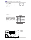
details. Also see the layout below for the
LED locations.
Infi niBand Link LED (LE3)
Color Status Defi nition
Yellow Solid Infi niBand:
Active
Yellow Dim Infi niBand:
Connected,
Activity: Idle
Off Off No connection
C