


2-12
X7DBT/X7DBT-INF/X7DGT/X7DGT-INF User's Manual
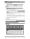
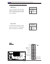
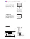
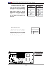
Overheat/Fan Fail LED (OH)
Connect an LED to the OH/Fan Fail
connection on pins 7 and 8 of JF1 to
provide advanced warnings of chassis
overheating or fan failure. Refer to the
table on the right for pin defi nitions.
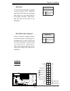
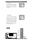
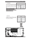
Power Fail LED
The Power Fail LED connection is
located on pins 5 and 6 of JF1. Re-
fer to the table on the right for pin
defi nitions.
OH/Fan Fail LED
Pin Defi nitions (JF1)
Pin# Defi nition
7 Vcc
8 Ground
OH/Fan Fail Indicator
Status
State Defi nition
Off Normal
On Overheat
Flash-
ing
Fan Fail
PWR Fail LED
Pin Defi nitions (JF1)
Pin# Defi nition
5 Vcc
6 Ground
A
B
A. OH/Fan Fail LED
B. PWR Supply Fail
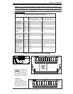
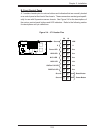
Power Button
OH/Fan Fail LED
1
NIC1 LED
Reset Button
2
HDD LED
Power LED
Reset
PWR
Vcc
Vcc
Vcc
Vcc
Ground
Ground
1920
Vcc
X
Ground
NMI
X
Vcc
PWR Fail LED
NIC2 LED
S
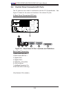
UPER X7DBT
LAN1
®
LAN2
Fan1/2
FP CTRL
SMB
Battery
North
Brid
ge
VGA
Infini-
U
SB0/1
JPG1
Sout
h
Brid
ge
DI
MM 1A (
Ban
k
1
)
JPL2
PCI-E x8
DIMM 1B
(
Ban
k
1)
D
IMM 2A (
Ban
k
2
)
DIMM 2B (
Ban
k
2
)
DIMM 3A
(
Ban
k
3)
DIMM 3B
(
Ban
k
3)
D
IMM 4A
(
Ban
k
4)
DIMM 4B
(
Ban
k
4)
JBT1
JWOR
JWOL
LAN
CTRL
SIMS0
L
E3
COM2
JPL1
SATA
3
J
I
2
C1
JI
2
C2
J7
JP1
JOH1
J
L1
4
-Pin
P
WR
BIOS
Buzzer
U
SB2/
3
CPU1
Fan
3
/
4
Fan
5
/
6
L
E
1
VGA
CTRL
S I/O
L
E
2
Band
INF
Ctrl
Video
Memory
J
1
SATA2
SATA
0
SATA1
CPU2
Fan
7
/
8
20-
Pi
n P
W
R
2
0-
P
inPWR
SG
PI
O
WD