


Chapter 2: Installation
2-19
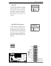
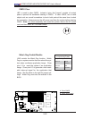
S
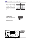
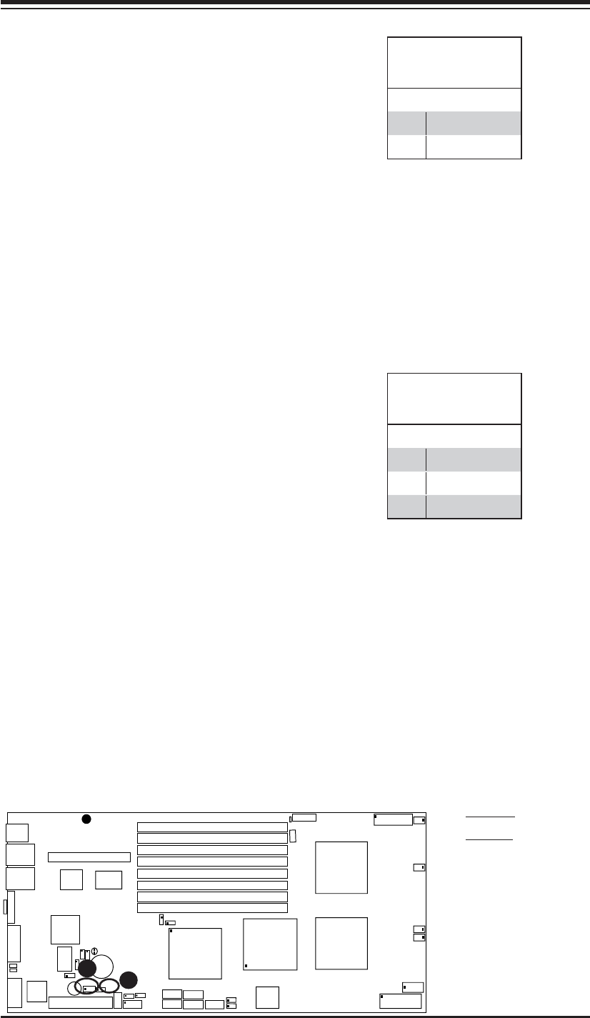
UPER X7DBT
LAN1
®
LAN2
Fan1/2
FP CTRL
SMB
Battery
North
Brid
ge
VGA
Infini-
USB0/1
JPG1
South
Bridge
DIMM 1A (Bank 1)
JPL2
PCI-E x8
DIMM 1B (Bank 1)
DIMM 2A (Bank 2)
D
I
MM 2B (Bank 2
)
DIMM 3A (Bank 3)
DIMM 3B (
Ban
k 3)
DIMM 4A (Bank 4)
DIMM 4B (Bank 4)
JBT1
JWOR
JWOL
LAN
CTRL
SIMS0
L
E3
COM2
JPL1
SATA
3
JI
2
C1
J
I
2
C2
J7
JP1
JOH1
J
L1
4-Pin
PWR
BIOS
B
uzz
er
USB2/3
CPU1
Fan3/4
Fan5
/6
LE1
VG
A
CTRL
S I/O
L
E2
Band
INF
Ctrl
Video
Memory
J1
SATA2
SATA0
SATA
1
CPU2
Fan7
/
8
20-
P
in PW
R
2
0-
P
inPWR
S
G
P
I
O
WD
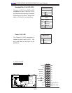
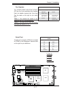
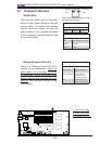
A. WOR
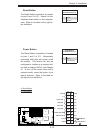
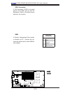
B. WOL
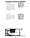
Wake-On-Ring
The Wake-On-Ring header is des-
ignated JWOR. This function allows
your computer to receive and be
awakened up by an incoming call to
the modem when the system is in
the suspend state. See the table on
the right for pin defi nitions. You must
have a Wake-On-Ring card and cable
to use this feature.
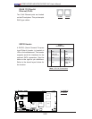
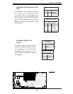
Wake-On-LAN
The Wake-On-LAN header is located
at JWOL on the motherboard. See the
table on the right for pin defi nitions.
(You must also have a LAN card with
a Wake-On-LAN connector and cable
to use this feature.)
Wake-On-Ring
Pin Defi nitions
(JWOR)
Pin# Defi nition
1 Ground
2 Wake-up
Wake-On-LAN
Pin Defi nitions
(JWOL)
Pin# Defi nition
1 +5V Standby
2 Ground
3 Wake-up
A
B