


Performance Tests
TDS 684A, TDS 744A, & TDS 784A Service Manual
4–53
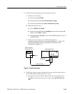
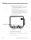
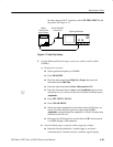
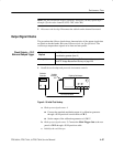
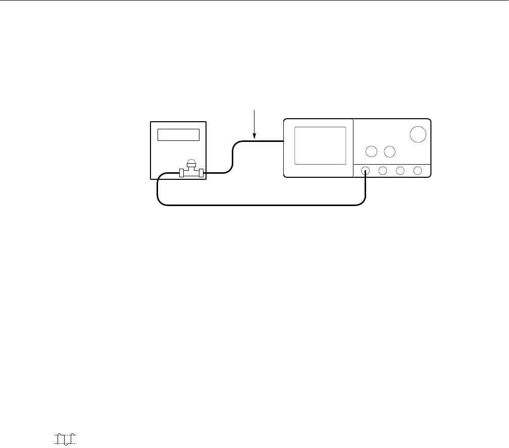
the other output of the T connector to the AUX TRIG INPUT
at the
rear panel. See Figure 4–17.
Medium
Frequency Sine
Wave Generator
Digitizing Oscilloscope
To AUX TRIG INPUT
on Rear Panel
Figure 4–17: Initial Test Hookup
2. Confirm Main and Delayed trigger systems are within sensitivity limits
(50 MHz):
a. Display the test signal:
H Set the generator frequency to 50 MHz.
H Press MEASURE.
H Press the main-menu button High-Low Setup; then press the
side-menu button Min-Max.
H Press the main-menu button Select Measrmnt for Ch1.
H Press the side-menu button –more– until Amplitude appears in the
side menu (its icon is shown at the left). Press the side-menu button
Amplitude.
H Press SET LEVEL TO 50%.
H Press CLEAR MENU.
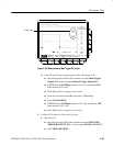
H Set the test signal amplitude for about three and a half divisions on
screen. Now fine adjust the generator output until the CH 1
Amplitude readout indicates the amplitude is 350 mV. Readout may
fluctuate around 350 mV.
H Disconnect the 50 W precision coaxial cable at CH 1 and reconnect
it to CH 1 through a 10X attenuator.
b. Check the Main trigger system for stable triggering at limits:
H Read the following definition: A stable trigger is one that is
consistent; that is, one that results in a uniform, regular display