


Removal and Installation Procedures
6–54
TDS 684A, TDS 744A, & TDS 784A Service Manual
5. Disassemble the chassis:
a. Set the assembly so its bottom is down on the work surface and its front
is facing you.
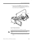
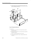
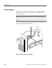
b. Remove the six screws securing the front subpanel to the main chassis.
(See Figure 6–24 for screw location.)
c. Lift the front subpanel up away from the main chassis.
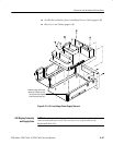
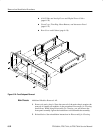
d. Now remove the five screws securing the rear chassis to the main chassis
and separate the two chassis. (See Figure 6–20 for screw location.)
6. Reassembly: Do the following substeps:
a. Reassemble the chassis: Align the rear chassis to the main chassis and
reinstall the five screws removed in step 5; align the front subpanel to
the main chassis and reinstall the six screws removed in step 5.
NOTE. The following substeps refer you to procedures for installing each module
removed. When reinstalling the modules, ignore any instructions that require
connecting a cable or bus to an module that you have not yet installed. The
necessary connections will be made when you install the missing module later.
b. Reinstall the inner-chassis modules: Do in the order listed the following
procedures. When doing these procedures, do their steps in reverse order.
These procedures are found under Procedures for Inner-Chassis Modules
which start on page 6–46.
H A30 Display Assembly and Supply Fuse (page 6–47)
H A16 Low Voltage Power Supply (page 6–46)
c. Reinstall the outer-chassis modules: Do in the order listed the following
procedures. When doing these procedures, do their steps in reverse order.
These procedures are found under Procedures for Outer-Chassis
Modules which start on page 6–29.
H Top Cover and Board Brackets (page 6–37)
H A11 Processor/Display Board (page 6–36)
H A23 SerPar Board (page 6–31)
H A29 Video Trigger Board – with option 05 (page 6–32)
H A14 D1 Bus and Analog-Power and Digital-Power Cables
(page 6–29)
H Fan (page 6–29)