


Troubleshooting
6–60
TDS 684A, TDS 744A, & TDS 784A Service Manual
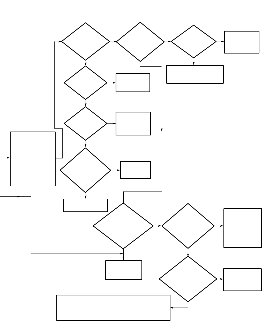
Replace the A17
Main LV Power
Supply module.
Replace the
A11 DRAM
Processor/Display
module.!
Yes
No
Does
DS1 flash .8,
then display the sequence
of hex numbers
pausing to
flash .c?
Press S1002 on the
A11 DRAM
Processor/Display
module towards the
back of the
oscilloscope and
cycle power.!
No
No
Perform the Display
troubleshooting
procedure.!
Yes
No
Power off the
oscilloscope and remove
its cabinet using the
Rear Cover and Cabinet
removal procedure. On
the A11 DRAM
Processor/Display
module, set S1001’s
eighth switch to the open
position.
Does DS1
first flash .8, then
display a sequence of hex
numbers from 1–e with no
period preceding
them?
Does
DS1 flash .8,
then display the sequence of
hex numbers
pausing to
flash .d?
Replace the A11 DRAM Processor/Display module.!
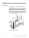
Note. The replacement module may not have the correct
firmware loaded. See page 6–58 for details on firmware updates.
Replace the
A11 DRAM
Processor/Display
module.!
Yes
No
Power
on again and
observe the LED
(DS1). Does it
only display
.8?
Yes
Is
there 5.1 V on
J27 pin 17? (See
Figure 6–32.)
Yes
No
Perform the A16 Low Voltage
Power Supply Module Isolation
troubleshooting procedure.!
No
Power
on again and
observe the LED
( DS1). Does it
display
.E?
No
Is
there~0 V on
J26 Pin 4? (See
Figure
6–32.)
No
Yes
Yes
Is
there~0 V on
J28 Pin 100?
(See Figure
6–32.)
No
Yes
Replace the
A11 DRAM
Processor/Display
module.
Is
there ~0 V
on U604 Pins 5,
7, 9, or 11 of the A10
Acquisition module?
(See Figure
6–35.)
No
Yes
Replace the
A15 Attenuator
module.
Replace the
A10 Acquisition module.
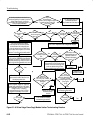
!Note. Set all the switches on S1001 back to the
closed position and cycle power before
performing another procedure.
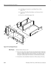
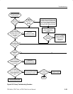
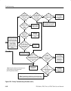
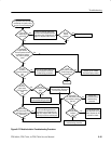
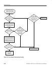
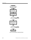
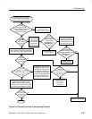
Figure 6–26: Primary Troubleshooting Procedure (Cont.)