


Troubleshooting
6–62
TDS 684A, TDS 744A, & TDS 784A Service Manual
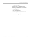
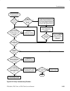
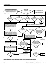
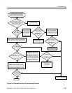
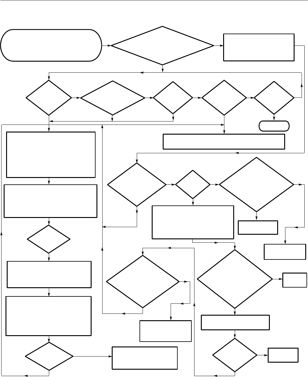
The oscilloscope may have
powered off because it
over-heated. Wait 5 minutes and
power on the oscilloscope.
Is the
fan’s connector
securely attached to J20
on the A11 DRAM
Processor/Display module?
(See Figure
6–33)
Is
there 25 V
across J27 pins 1
and 3 on the A11 DRAM
Processor/Display module?
(See Figure
6-32.)
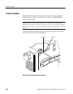
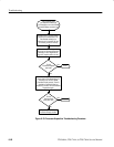
Turn off the principal power switch.
Disconnect the line cord from its power
source. Remove the oscilloscope rear
cover and cabinet using the Rear Cover
and Cabinet removal procedure. Connect
the oscilloscope to the correct power
source. Turn on the principal power switch.
Use this procedure to determine if an
oscilloscope problem is caused by the Low
Voltage Power Supply. Connect the
oscilloscope to the correct power source. Turn
on the principal power switch.
No
Yes
Is fuse blown?
Are
the front-panel
lights
on?
Yes
No
Replace
fuse. Does fuse
blow again?
Yes
Turn off the power switch. Disconnect the line cord from its
power source. Replace the Low Voltage Power Supply
.
No
Turn off the principal power switch.
Remove the two power cables from the
right side of the oscilloscope. Turn on
the principal power switch.
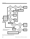
Without a power supply load, check the
power supply voltages on the A17 Main
LV Power Supply module (see Table 6–6
and Figure 6-32). If necessary,
temporarily short pins 3 and 5 of J5 to
toggle the On/Standby Control circuit.
The Low Voltage Power Supply
is ok. Perform the Primary
troubleshooting procedure.
No
Yes
Yes
Check the power supply voltages on J26 and
J27 on the A11 DRAM Processor/Display
module (see Table 6–5 and Figure 6-32). If
necessary, temporarily short pins 3 and 5 of
J26 to toggle the On/Standby Control circuit.
No
Press
the ON/STBY button.
Are the front-panel
lights on?
No
Yes
Does the
oscilloscope
work?
No
Done.
Are
the voltages
ok?
Yes
Are
the voltages
ok?
No
Yes
Does
it power on
normally and pass
all the
diagnostics?
Yes
No
Is
the fan
working?
No
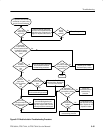
Turn off the principal power switch.
Disconnect the line cord from its power
source. Remove the oscilloscope rear
cover and cabinet using the Rear
Cover and Cabinet removal procedure.
Yes
Unplug the fan, power on the
oscilloscope and probe J20.
Is
there 25 V
across the pins
of J20?
Yes
Replace the
fan.
Yes
Replace the A11 DRAM
Processor/Display
module.
Does the
oscilloscope have
adequate ventilation (as
specified in Section 2
Operating Information
on page 2–3)?
Create adequate
ventilation.
No
No
Connect
the fan.
Yes
No
Replace the A10
Acquisition module.
Yes
No
Does
the oscilloscope
power on, all the diagnostics pass,
but sometime later it powers off
on its own?
Figure 6–28: A16 Low Voltage Power Supply Module Isolation Troubleshooting Procedure